

This factory service manual covers the Gehl 721 and 721T (Telescopic) wheel loaders, and also documents the related 621, built on Manitou Americas models 303-00, 304-00, and 303-10. Publication 50940188, it runs 134 pages and is powered by the Perkins 1004-42 diesel engine.
The manual is organized by system: maintenance, engine, the hydrostatic power train, axles, brakes, steering, the electrical system, and the work hydraulics. Each section carries specifications, tightening torques, diagrams, and inspection protocols.
Owners and independent mechanics can use it to plan maintenance, set injection and valve figures, diagnose drive and transmission faults, adjust the brakes and steering sensors, and trace the hydraulic circuits. It is a downloadable PDF you can read on a device or print for the workshop, matched to the exact models and serial ranges the machine carries.
What's Inside This Manual
| System | Pages | Key Topics |
|---|---|---|
| Maintenance | 4-13 | Engine Fluids and Lubricants, Maintenance Kits, Maintenance Plan 621/721 (Model 303-00/304-00), Maintenance Plan 721 Telescopic (Model 303-10) |
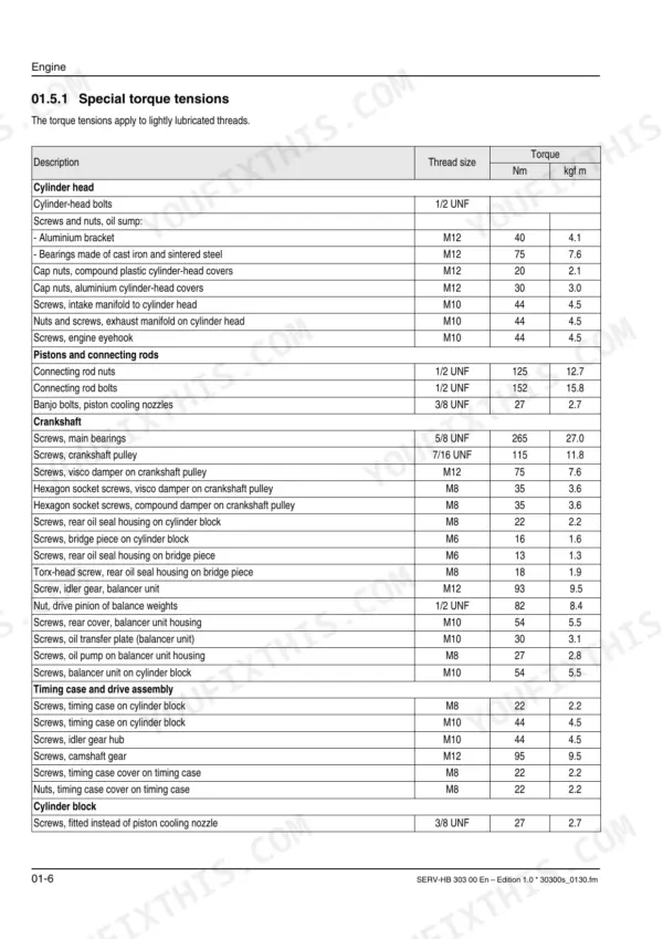
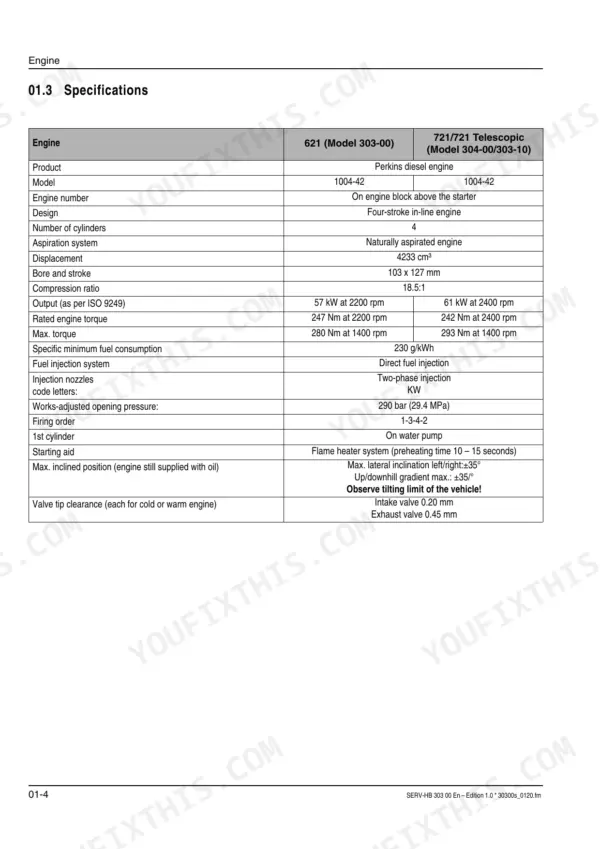
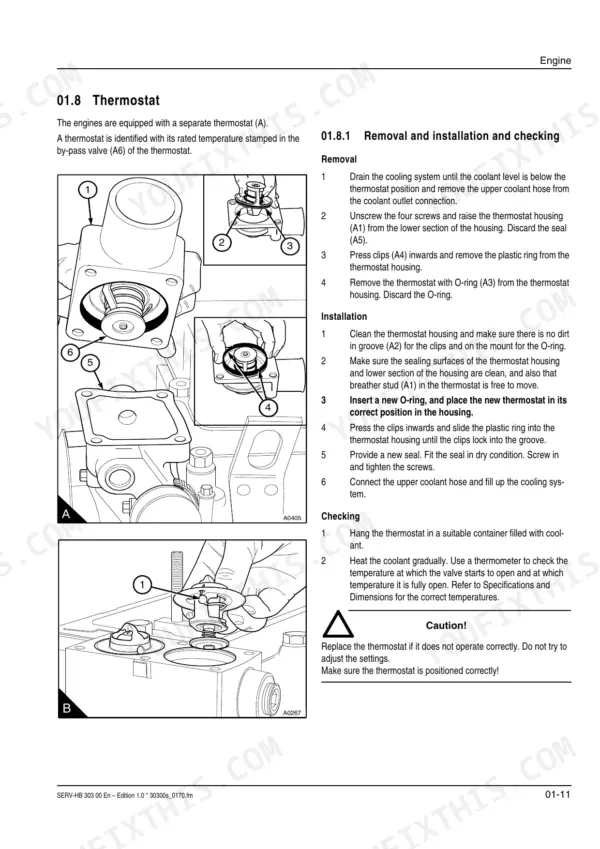
| Engine | 14-29 | Engine: Overview, Safety, Specifications, Tightening Torques, Crankcase Breather, Fuel System |
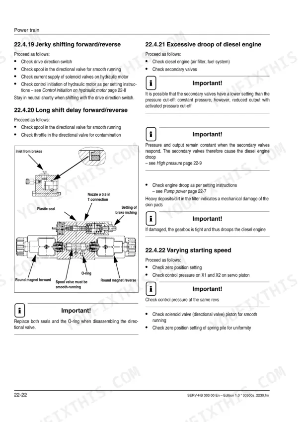
| Power Train | 30-57 | Variable Displacement Motor – Overview, Solenoid Valve – Driving Direction, Hydraulic Circuit – Drive, Adjustment Work on Drive, Towing, Hydraulic Motor |
| Axles | 58-79 | Type Label – Axle, Rear Axle Tightening Torques, Planetary Drive, Differential Input Shaft, Planetary Carrier, Axle Tube and Differential, Gearbox Sealing Work |
| Brakes | 80-87 | Overview – Parking Brake, Brake Caliper – Adjustment, Service Brake, Brake Hydraulic Circuit, Brake Diagram, Service Brake – Component Parts |
| Steering | 88-93 | Overview – Steering Circuit, Steering Circuit, Steering Ram Front axle/rear Axle, Adjusting the Steering Sensors |
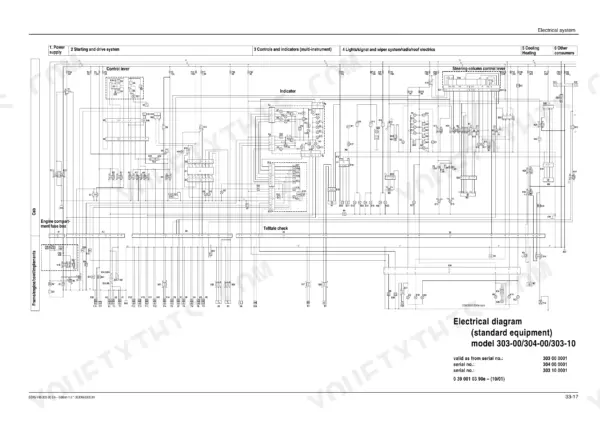
| Electrical System | 94-103 | Ohm's Law (Current, Voltage, Resistance); Power, Measuring Equipment, Measuring Methods, Terminal Description, Relay, Electrical Equipment, Electronics Box |
| Electrical Diagrams | 104-113 | Wiring Harness Engine And Frame, Wiring Harness – Cab, Wiring Diagram – Options |
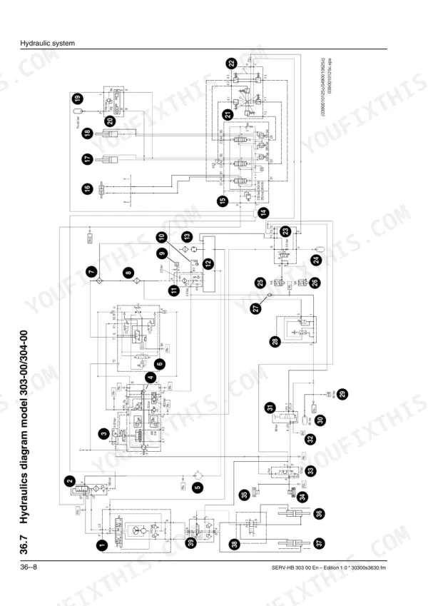
| Hydraulic System | 114-134 | Control Valve Circuit – Loader Unit Model 303-00/304-00, Hydraulic Pump – Hydraulic Oil Tank Model 303-00/304-00 Circuit, Joystick – Control Valve Model 303-00/304-00 Circuit |
Quick Reference Specifications
| Specification | Value | Page |
|---|---|---|
| Standard tightening torques for screws and nuts (M10 x 1.50) | 44 Nm (4.5 kgf m) | p. 20 |
| Hydraulic oil filter insert replacement interval | every 12 months or 1200 service hours | p. 10 |
| Fuel filter (prefilter and main filter) replacement interval | every 50 service hours / weekly | p. 8 |
| Air filter insert replacement interval | every 3rd change of air filter insert and every 12 months or 1200 service hours | p. 8 |
| Flexible lines replacement interval | every 6 years (UVV, DIN 20066 T5) | p. 10 |
| Cylinder seal kits | Replacement indicated when damaged or during overhaul, specific clearance or torque values for the kits are not provided. | p. 67 |
| Drive belts | Condition and pretension to be checked, retightened or replaced if necessary. Specific values not provided. | p. 9 |
| Coolant hoses | Condition and pretension to be checked, retightened or replaced if necessary. Specific values not provided. | p. 9 |
| Battery specifications | 12 V/88 Ah (354x175x190 mm) | p. 100 |
| Forward high pressure at control piston when pressure suddenly drops (Control initiation on hydraulic motor) | approx. 290 – 300 bar | p. 39 |
| Engine oil capacity | 11 l | p. 6 |
| Hydraulic oil tank capacity | about 90 l | p. 6 |