


Part of the Case IH Repair Manuals.
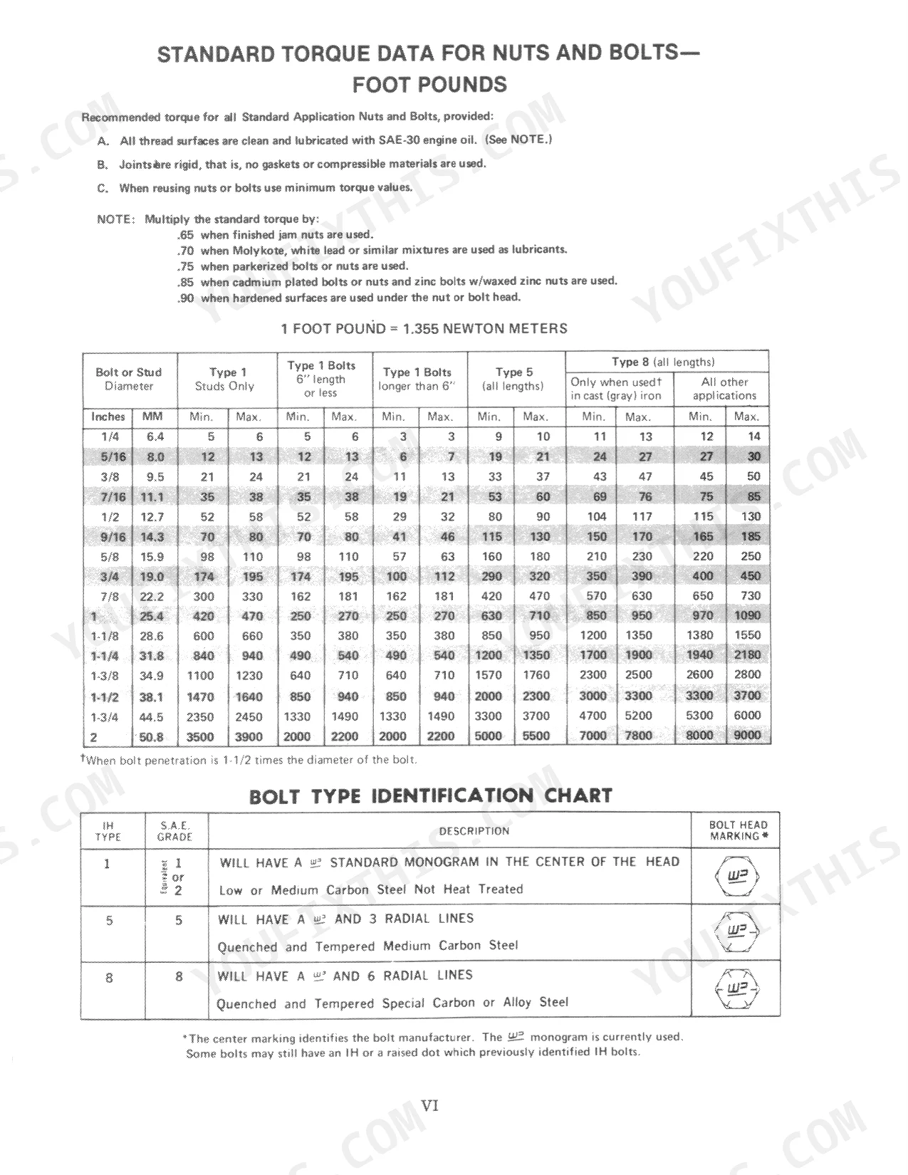
This 603-page International Service Manual (OEM #GSS14703) covers the 786, 886, 986, 1086, 1486, 1586, and Hydro 186 tractors, every system from front axle to closed-center hydraulics. Open it up and you get full wiring diagrams for the cab and instrument cluster, hydraulic schematics covering open-center and closed-center load/position control circuits, and a dedicated troubleshooting section for chasing electrical and hydraulic faults. You also get torque tables, exploded views for the transmission and differential, and step-by-step calibration procedures for the hydraulic system analyzer. Set RPM and MPH transducer lock nuts to 9-11 ft. lbs., and torque the unloading valve body to 47-54 N·m (35-40 ft. lbs.) before you button it back up. No more cross-referencing three parts books to find the right number. This PDF is bookmarked by section, so pull it up on your phone and jump straight to the hydraulic test procedures.
What's Inside This International 786–1586 + Hydro 186 Manual
| System | Pages | Key Topics |
|---|---|---|
| Safe Work Rules, Standard Torque Data, Metric Conversion Tables, Special Service Tools Required | 9-21 | Safe Work Rules, Danger, Warning, Caution, Standard Torque Data for Nuts and Bolts, Metric Conversion Tables, Standard Torque Data for Hydraulic Tubes and Fittings, Special Service Tools Required |
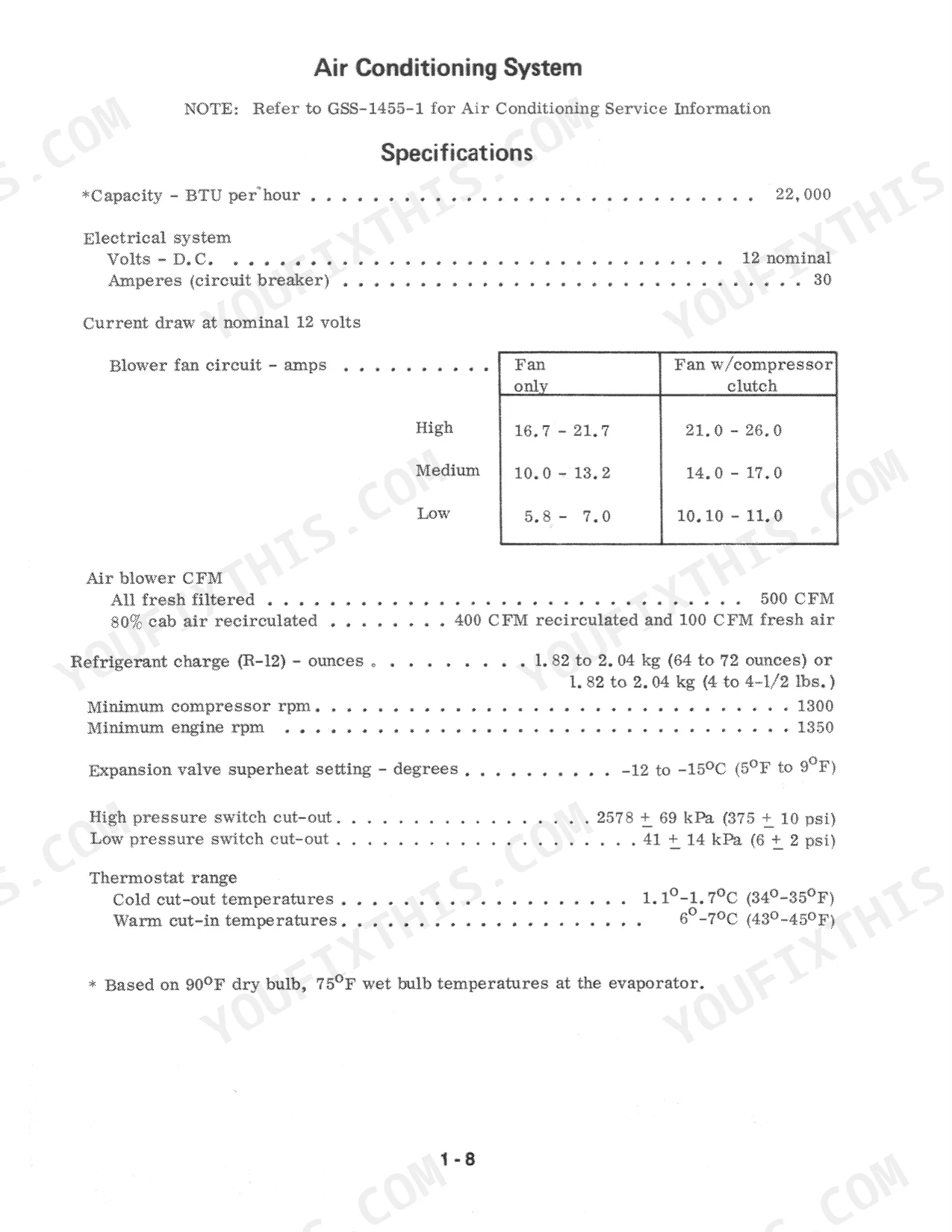
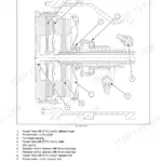
| Cab, Air Conditioning and Splitting the Tractor | 22-81 | Control Center, Air Conditioning System, Windshield Wiper Motor, Recirculation Door and Adjustment Rod Removal, Split Between the Engine and Speed Transmission, Tractor Ballast |
| Font End, Axle and Wheels | 82-167 | Front Axle Service, Steering Arm Adjustment, Adjusting Toe-In, Wheel Ends, Differential, Drive Line |
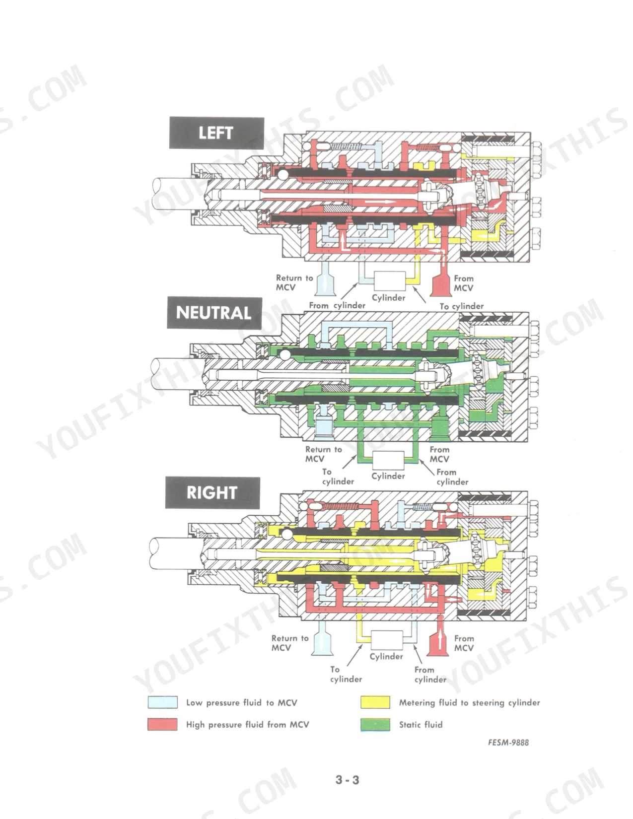
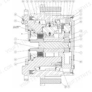
| Steering | 168-197 | Power Steering, Control Valve, Metering Section, Steering Wheel and Shaft, Steering Hand Pump, Power Steering Cylinder |
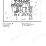
| Engine | 198-199 | - |
| Fuel System | 200-205 | Main Fuel Tank, Auxiliary Fuel Tank, Auxiliary Fuel Tank Fitting Installation |
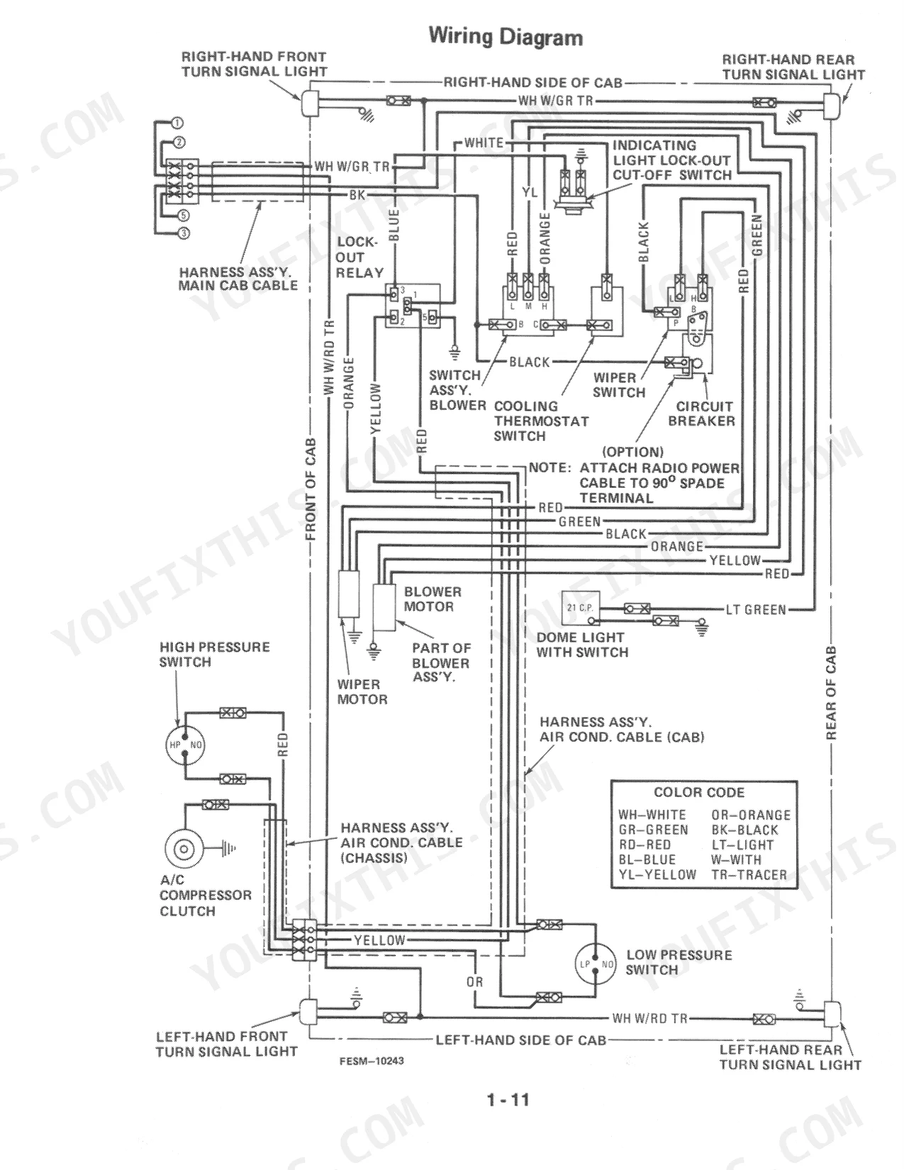
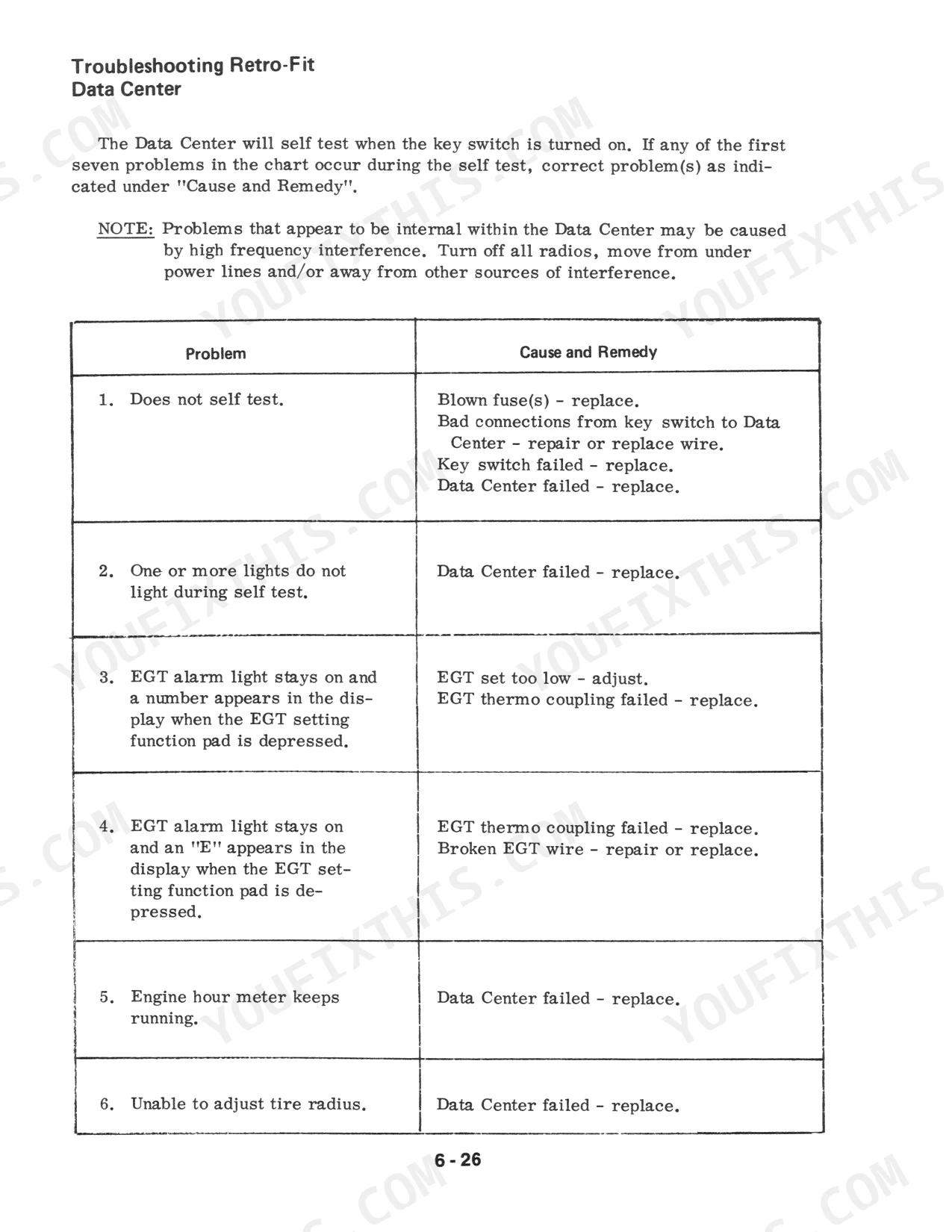
| Electrical System | 206-237 | Digital Monitor, Digital Data Center, Transducer, Instrument Gauge, Wiring Diagrams, Cab Wiring Diagram |
| Cooling System | 238-239 | - |
| Clutch and FlyWheel | 240-251 | Clutch Specifications, Clutch Assembly, Clutch Booster Assembly, Clutch Linkage Adjustment, Ta Spool Adjustment, Neutral Starting Switch Adjustment |
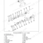
| Transmission | 252-325 | Special Torques, Power Flow Gear Drive, Speed Transmission, Clutch Housing Repair Procedure, Torque Amplifier, Ipto Drive Shaft |
| Differential | 326-333 | Special Torques, Pinion Mounting Distance Set Up, Adjusting Bearings, Adjusting Backlash, Differential Lock |
| Rear Axle, Housing and Wheels | 334-351 | Special Torques, Rear Axle and Bull Pinion Shaft, Bull Pinion Shaft Bearing Adjustment, Axle Outer Bearing Pre-Load Adjustment, High Clear Drop Housing, Planetary Assembly |
| Brakes | 352-369 | Specifications, Power Hydraulic Multi-Disc Brakes, Brake Service, Bleeding the Brakes, Power Brake Valve, Brake Pedal and Linkage Adjustment |
| Independent Power Take Off | 370-405 | Specifications, Ipto Introduction, Servicing Ipto Components, Ipto Pump, Ipto Clutch Pack Assembly, Ipto Control Valve |
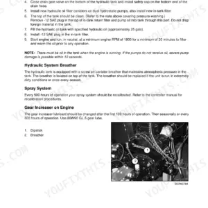
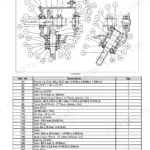
| Hydraulic System | 406-535 | Basic Hydraulic System, Open Center Load and Position Control Hitch and Auxiliary Hydraulic System |
| Testing and Hydraulic System | 536-603 | Specifications, Test No. 1 (Pph - Closed Center System), Hydraulic System Analyzer (14-557) Installation (Pph - Closed Center System) |
Quick Reference Specifications
| Specification | Value | Page |
|---|---|---|
| RPM Transducer torque | 9-11 ft. lbs. | p. 235 |
| MPH Transducer torque | 9-11 ft. lbs. | p. 235 |
| Unloading valve body torque | 47 to 54 N·m (35 to 40 ft. lbs.) | p. 469 |
| Countershaft Bearing End Play | .000 to .229 mm (.000 to .009 inch) | p. 301 |
| Drawbar settling limit | not lower more than .2 inch in one minute | p. 534 |
| Speed Transmission Countershaft Nut Torque | 406 N·m | p. 254 |
| Range Transmission Mainshaft Retaining Nut Torque | 136 N·m | p. 254 |
International 786–1586 + Hydro 186 Common Problems This Manual Covers
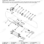
Hitch lift arms settle or sag within a minute or two after being raised and locked
Run the position control accuracy test and time how far the drawbar settles after raising the hitch. Replace seals in the lift cylinder or check valve if it lowers more than .2 inch in one minute, the limit specified on page 534. Inspect the rockshaft linkage and load control valve for internal leakage before reassembly.
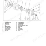
Manual Section: Hydraulic System p. 534Hydraulic hitch raises slowly, surges, or fails to hold position when carrying heavy implements
Remove the unloading valve body and inspect the seal washer, poppet, and spring for wear or debris. Install new O-rings and torque the valve body to 47-54 N·m (35-40 ft. lbs.) per page 469. Reassemble the spring, poppet, piston, and plug, then cycle the hitch to confirm it holds position without drift.
Manual Section: Hydraulic System p. 469Countershaft bearing in transmission binds or runs rough before reaching full torque spec
Remove the trunnion bearing cage and check the shim stack thickness. Set bearing end play to .000-.229 mm (.000-.009 inch) as specified on page 301, adding or removing shims until the cage rotates freely. Re-torque the countershaft nut to 406 N·m (300 ft. lbs.) per page 254 and confirm there's no binding before reinstalling the cover.
Manual Section: Transmission p. 301Frequently Asked Questions
What are the replacement specifications for RPM Transducer (flywheel-mounted)?
For the RPM transducer located at the flywheel, turn the transducer counter-clockwise 1/2 to 2/3 turn and secure the lock nut with 9-11 ft. lbs. of torque during installation. This ensures proper adjustment after contacting the gear tooth. p. 235
What are the replacement specifications for Position Transducer (MPH transducer with O-ring)?
When installing the MPH transducer, add an O-ring to the transducer. Turn the transducer counter-clockwise 1/4 to 1/3 turn after it contacts the gear tooth, then secure the lock nut with 9-11 ft. lbs. of torque. p. 235
How do you fix case IH tractor stalling or losing RPM under load when engaging PTO or lifting heavy loads?
Check the RPM transducer at the flywheel for misalignment or wear. Turn the transducer counter-clockwise 1/2 to 2/3 turn until it seats against the flywheel, then secure the lock nut to 9-11 ft. lbs. per the transducer specs on page 235. Replace the transducer if the engine still loses RPM under load. p. 235
How do you fix hydraulic lift control feels inaccurate or hitch doesn't respond consistently to lever position?
Inspect the MPH transducer at the rear frame for wear or incorrect seating. Turn the transducer counter-clockwise 1/4 to 1/3 turn until it bottoms out, then torque the lock nut to 9-11 ft. lbs. as specified on page 235. Check the digital monitor's MPH reading against actual ground speed before returning the tractor to service. p. 235
Is this Service Manual a digital download?
You get a 603-page searchable PDF that downloads instantly after checkout. Open it on your laptop, tablet, or phone, and bring it right to the shop floor.
Are there any print restrictions on this manual?
Yes, print as many copies as you want, and there are no restrictions. Many mechanics print the section they need and bring it to the shop floor.
Are electrical wiring diagrams included in this International 786 & variants manual?
Yes, full electrical schematics are included with wire colors, connector locations, and circuit descriptions.


Reviews
There are no reviews yet.