


Part of the Case IH Repair Manuals.
All 1,502 pages of this Case IH WD1903, WD2303 Repair Manual (OEM #87738745) are factory-written for one purpose: getting your Self-Propelled Windrower back to factory spec without guesswork. Inside you get full hydraulic schematics that trace fluid routing through the hydrostatic transmission, header drive, and lift circuits, plus wiring diagrams covering every harness, relay, and sensor pinout across both models. Open to the electrical section and you will find fault code tables for the XCM controller, step-by-step diagnostic charts for mechanical and electrical faults, and torque data for hydraulic fittings, gearbox hardware, and brake assemblies. Fill the fuel tank to 454 L, top off the hydraulic reservoir to 54.9 L, and charge the A/C with exactly 2.2 kg of R134a. Every hour your machine sits costs money. Search by keyword, hit a bookmark, and get straight to the procedure.
What's Inside This Case IH WD1903, WD2303 Repair Manual
| System | Pages | Key Topics |
|---|---|---|
| General Information | 45-66 | Precautionary Statements, Safety, Product Identification Numbers, Engine Pin Number, Company Policy, Parts and Specifications, Lubrication |
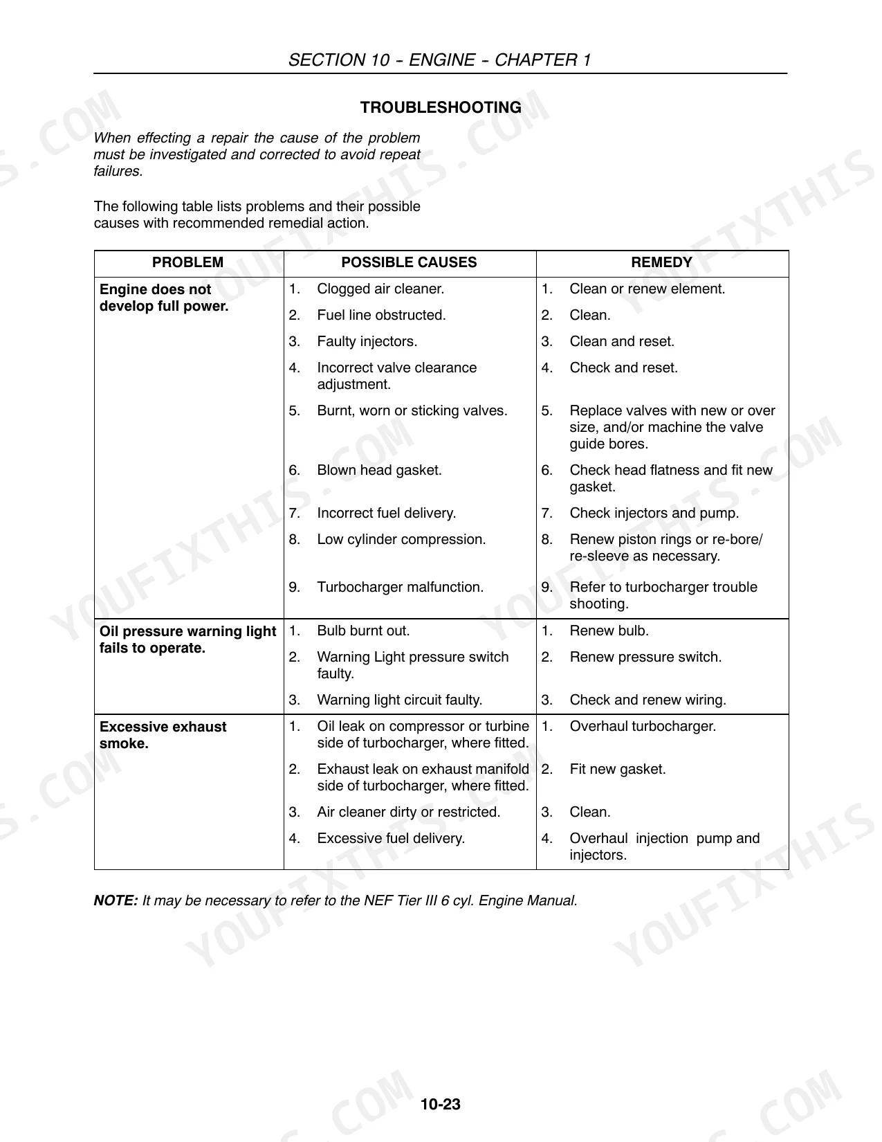
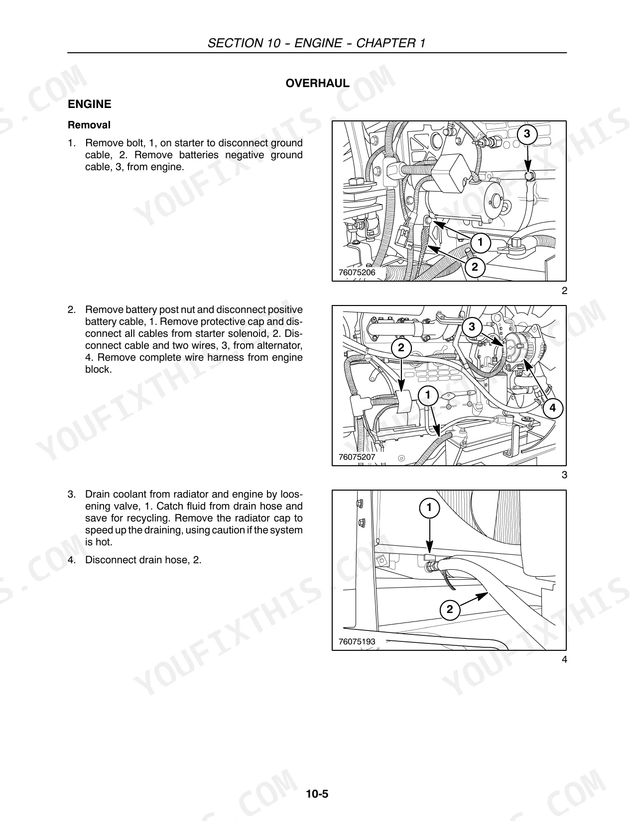
| Engine | 67-126 | Specifications, Operation, Cylinder Block Assembly, Engine Overhaul, Removal, Installation, Troubleshooting, Fuel System |
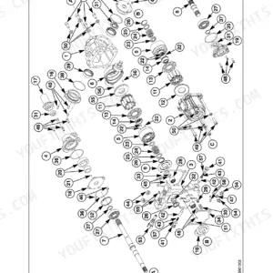
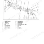
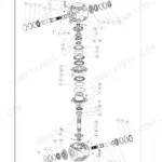
| Drivetrain (Front Mechanical Drive & Hydrostatic Transmission) | 127-270 | Special Tools, Planetary Gearbox Drive, Disassembly, Assembly, Hydrostatic Transmission Identification, Torque Specifications, Motor Area |
| Brakes and Controls | 271-288 | Special Tools, Brake Assembly, Removal, Installation, Disassembly, Rotating/Stationary/Primary Disc Assembly, Brake Bleeding Procedure |
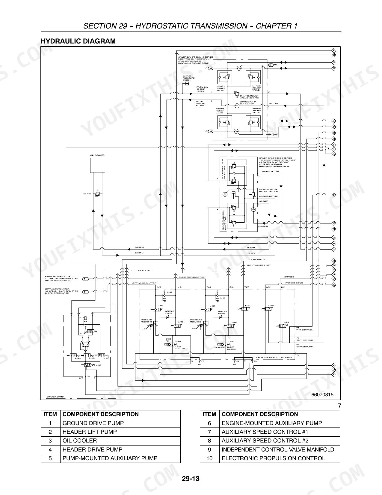
| Hydraulic Systems | 289-474 | System Component Locations, Diagram Symbols, Hydraulic System Diagram, Ground Drive Theory of Operation, Hydraulic Bleed Procedure, Circuit Diagrams |
| Rear Axle | 475-522 | Special Tools, Specifications, Extensions and Axle Tube, Wheel Width Adjustments, Extension Widths, Axle Extension Position |
| Climate Control | 523-610 | Compressor, Refrigerant, Refrigerant Oil, Special Tools |
| Electrical Diagnostics & Wiring | 613-673 | Troubleshooting Charts, Electrical Schematics, LCD/Display Module, Alarms, Multimeter, Fuse Panel Identification, Circuit Breakers, Relays, Diodes, Wiring Harnesses and Connectors, Ground Distribution System, Xcm Power Distribution |
| Air Conditioning Systems | 674-707 | Manual and Atc Systems, Manual HVAC System (Standard), Operation |
| Lighting Systems | 708-739 | Lamp Replacement Chart, Flashing Lights and Turn Signals, Road Lights, Tail Lights, Work Lights, Stubble Lights, Console and Dome Lights |
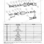
| Electrical Components, Sensors & Battery | 740-788 | Electronic Control Unit Pinout Diagrams, Crankshaft Sensor, Camshaft Sensor, Boost Temperature-Pressure Sensor, Engine Oil Temperature-Pressure Sensor, Rail Fuel Pressure Sensor, Electro-Injectors, Grid Heater, Engine Starting Motor Circuit, Coolant Temperature Sensor, Fuel Temperature Sensor, Battery Charging and Testing |
| Alternator | 789-1360 | Charging System Excitation Circuit Operation |
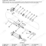
| Header Attachments | 1361-1456 | Draper Floatation, Cut Height Cylinders, Removal, Inspection, Installation, Control Valve Manifold |
| Cab, Platform & Optional Equipment | 1457-1502 | Deluxe Operator's Seat, Seat Height/Weight Adjustment, Backrest Angle, Seat Suspension System, Deluxe Cab Upgrade Package, A-Pillar Display, Radio, Cold Start Kit |
Quick Reference Specifications
| Specification | Value | Page |
|---|---|---|
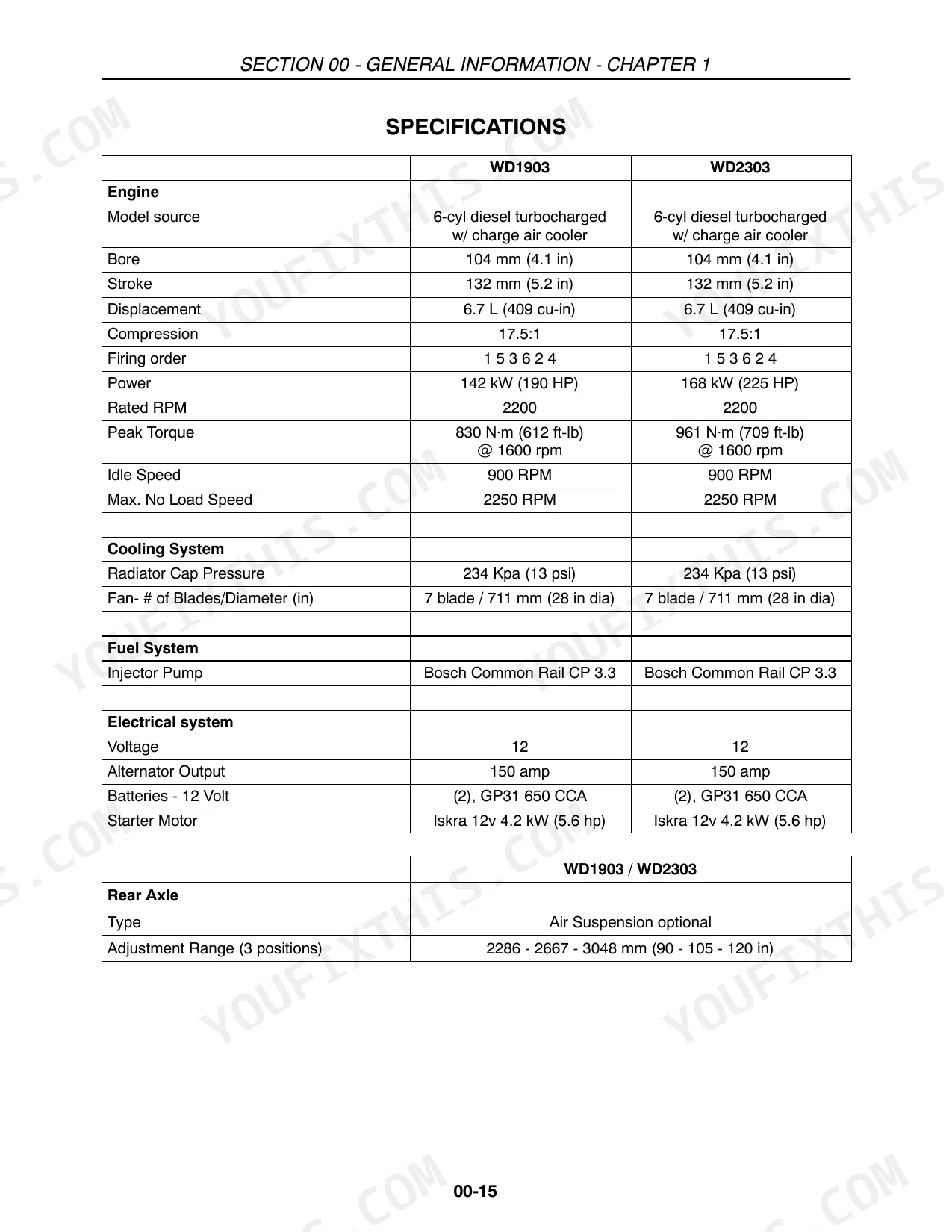
| Engine Bore | 104 mm | p. 59 |
| Radiator Cap Pressure | 234 Kpa | p. 59 |
| Fuel Tank Capacity | 454 L | p. 61 |
| Hydraulic System Reservoir Capacity | 54.9 L | p. 61 |
| A/C System (R134a) Capacity | 2.2 kg | p. 61 |
| Rear Axle Extension Bolts Torque | 960 N⋅m | p. 477 |
| Hydrostatic Pump Relief Setting (system warm) | 383.3 bar | p. 154 |
| Charge Pump Relief Setting | 20 bar | p. 154 |
| Case Pressure (Continuous) | 1.7 bar | p. 154 |
| Air Spring Working Pressure | 172 - 276 kPa | p. 501 |
| Single-speed Motor to Wheel Housing Torque | 137 N⋅m | p. 156 |
| Header Lift Pump Output Capacity | 20.4 L/min | p. 321 |
Case IH WD1903, WD2303 Common Problems This Manual Covers
Loss of header lift flotation on slopes, header sags into the crop
Check hydraulic reservoir level first; total system capacity is 54.9 L (page 61) and low fluid directly starves the header lift circuit on slopes. Test the master hydraulic solenoid coil resistance per page 632. Verify header lift pump output; rated flow is 20.4 L/min (page 321). Run the hydraulic bleed procedure on page 289 if air has entered the circuit.
Manual Section: Hydraulic Systems p. 289Hydrostatic transmission overheats on long runs in summer heat, machine slows to a crawl
Verify charge pressure is at least 20 bar (page 154); low charge pressure causes cavitation and rapid overheating. Check hydrostatic oil level and inspect for burnt or contaminated fluid. Clean the oil cooler of crop debris. Confirm the system pump relief setting of 383.3 bar (page 154) is not bypassing continuously under load.
Manual Section: Hydrostatic Transmission p. 151Engine turns over normally but won't fire in cold weather below freezing
Verify battery voltage before attempting to start; below 11.0 V requires slow charging before cranking (page 784). Confirm the grid heater relay activates during the preheat cycle per page 749. Inspect the fuel water separator for gelled or waxed diesel. Check the starting motor circuit on page 750 to confirm all safety interlocks are closed.
Manual Section: Engine Starting Motor Circuit p. 750Cab A/C blows warm air, insufficient cooling even on maximum fan speed
Check refrigerant charge first; the system requires 2.2 kg of R134a (page 61) and low charge is the most common cause of warm air at any fan speed. Inspect the condenser core for crop debris and clean it. Test compressor clutch engagement. Follow the no-cooling diagnostic flow in the Climate Control section starting page 523.
Manual Section: Climate Control p. 523Frequently Asked Questions
How to reset header float on Case IH WD1903?
To adjust the header float, access the "Dealer Setup Menu" by pressing and holding buttons, 1, on the MFH for about seven (7) seconds until "Dealer Setup" is displayed. Then, navigate to "User Configure" and select "Float Adjust?" to make the necessary adjustments. p. 1452
How to reset transmission fault code on WD2303?
To reset a transmission fault code, navigate to the "Fault History" screen in the "Dealer Setup" menu. Move the pointer to "Clear Fault Code?" and press and hold the ENTER key for one second to clear the specific fault. To clear all fault codes, scroll to "Clear All Faults?" and hold the ENTER key for one second. p. 849
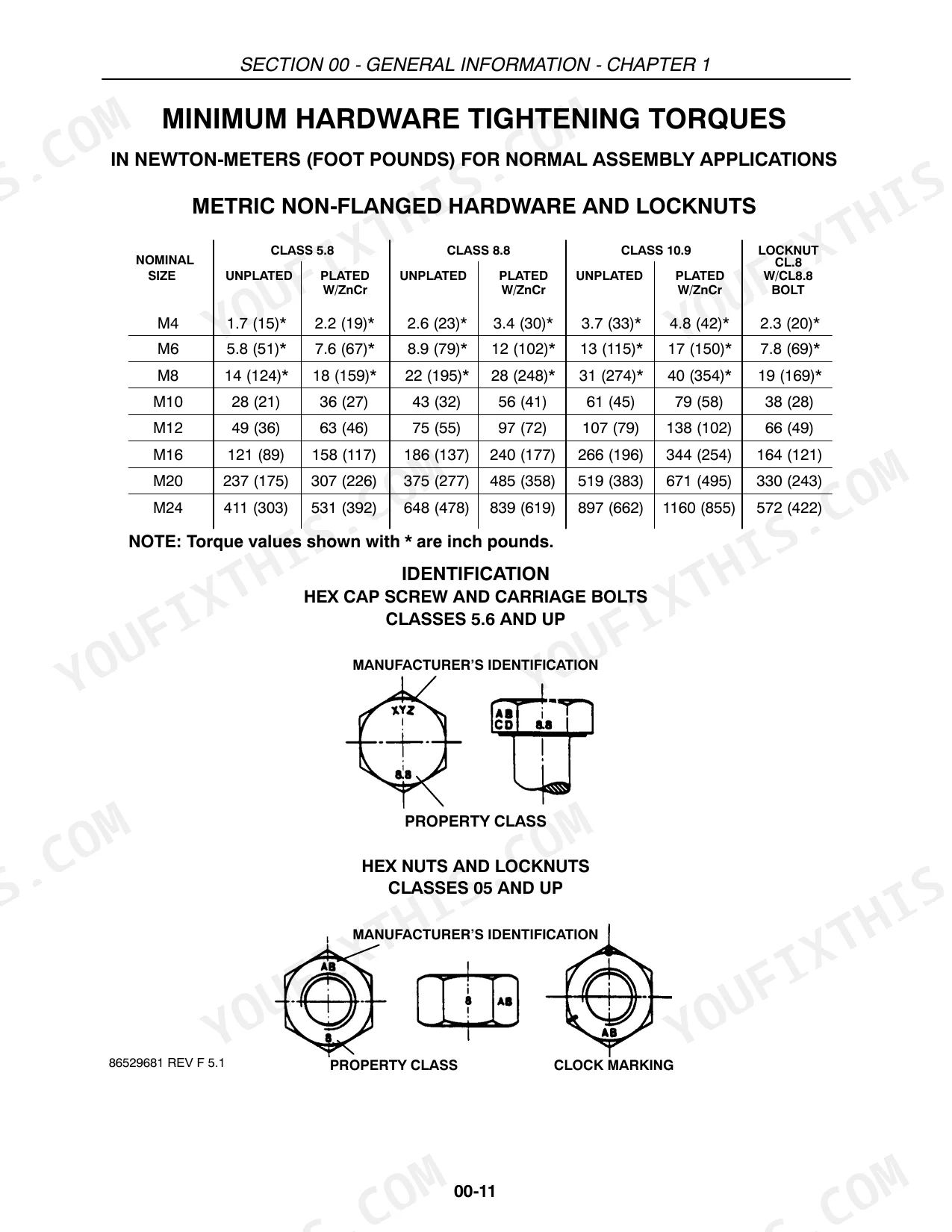
Torque specifications for WD2303 front axle mounting bolts?
When installing the final drive onto the main frame, secure it with eight 5/8″× 1-3/4″ cap screws and flat washers. Torque these fasteners to 224 N⋅m (165 ft-lbs). p. 136
How do you fix case IH WD2303 engine loses power under load, won't run reliably through a full commercial day?
Check the air filter restriction indicator and inspect the filter element; a clogged element starves the turbo and kills power under sustained load. Verify the fuel water separator is clear of contamination. Confirm the tank has adequate fuel (system capacity 454 L, page 61). Work through the low-power diagnosis steps in engine troubleshooting.
How quickly can I access this manual after buying?
This is a 1502-page searchable PDF ready for immediate download. Works on any device, so pull it up on your phone while you're under the hood. No shipping, no waiting.
Am I able to print pages from this manual?
Yes, print as many copies as you want, and there are no restrictions. Many mechanics print the section they need and bring it to the shop floor.
Are there hydraulic schematics in this Case IH WD1903, WD2303 manual?
Full hydraulic system diagrams are included, covering circuits, valve locations, and hydraulic component specs for the Case IH WD1903, WD2303.


Reviews
There are no reviews yet.