


Part of the Case IH Operator Manuals.
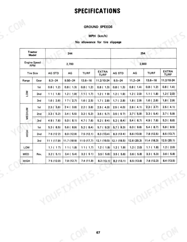
Pull up the International Harvester 244, 254 Operator Manual PDF (OEM #1258524C3) and you're looking at 84 pages of factory-direct operating procedures, safety rules, and maintenance schedules built specifically for these two tractors. Inside: a full controls section walking through every instrument panel indicator, brake pedal, PTO lever, differential lock, and hydraulic flow control on the tractor. You get a detailed safety chapter covering startup, operation, transport, and post-upset procedures, plus torque tables for front and rear wheel hardware. Top off the transmission and hydraulic system to 22.2 quarts (21L) and torque rear wheel bolts between 81 and 97 ft-lbs (118-131 N-m) before you go to the field. Your machine isn't guessing. Neither should you. Download, open on your tablet, and bring the factory answer right to the tractor.
Complete the set for your 244, 254
- Repair Manual: Case IH 234, 244, 254 Service Manual — Wiring Diagrams
What's Inside This Case IH 244, 254 Operator Manual
| System | Pages | Key Topics |
|---|---|---|
| To the Owner | 3-4 | Park Brake Lever, Seat |
| Serial Number | 7 | Right Side of Front Axle Bracket, Tractor Serial Number Also Identified at Right Side of Transmission Housing, Right Side of Engine Crankcase, 244 Tractor with K3D Engine |
| Terms and Location | 8 | Front, Right, Rear, Left |
| Work Safely - Follow These Rules | 9-12 | Servicing and Before Starting, Starting, During Operation, Transporting, Tractors Without ROPS, Before Dismounting, Dismounting, After an Upset |
| Energy Conservation - Follow These Recommendations | 13-14 | Valve Adjustments, Fuel Injection Pump Timing, Air Filter Servicing, Fuel System Leaks, Tire Inflation, Ballast |
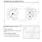
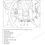
| Instruments and Controls | 15-23 | Instrument Panel and Controls, Brake Pedals, Brake Latch, Clutch Pedal, Differential Lock Pedal, Hydraulic Flow Control, Engine Speed Control Lever, Foot Accelerator Control |
| Optional Instruments and Controls | 24 | Rear Work Lamp, Draft Control, All-Wheel Drive |
| Before Operating Your Tractor | 25 | Fuel Tank, Engine Oil Level, Transmission Oil Level, Radiator Coolant Level, Tire Inflation Pressures, Tellites |
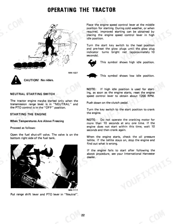
| Operating the Tractor | 26-29 | Neutral Starting Switch, Starting the Engine, Tractor Break-In Procedure, With the Engine Running, Stopping the Engine, Steering the Tractor, Driving the Tractor |
| Engine and Fuel System | 30-32 | Warranty Notice, Fuel System, Fuel Filter, Fuel Injection Pump and Nozzles |
| Cooling System | 33-34 | Coolants and Cooling System Conditioner, Checking the Coolant Level, Draining the Cooling System, Filling the Cooling System, Hoses and Clamps, Thermostat, Cleaning the Radiator |
| Air Cleaning System | 35 | Removing the Dust Pan and Air Filter Element, Cleaning the Element, Inspection |
| Electrical System | 36-40 | Charging System for Alternator-Generator, Cranking System, Lighting System |
| Hydraulic Controls for Three - Point Hitch | 41 | Position Control Lever, Hitch Drop Rate Adjustment and Lock, Hydraulic Flow Control Knob |
| Three - Point Hitch | 42-44 | Lift Links and Turnbuckles, Hitch Upper Link, Stabilizer Chain, Coupling the Equipment, Uncoupling the Equipment |
| Operating the Three Point Hitch with Draft Control | 45 | Position Control Lever, Draft Control Lever, Upper Link Adjustment, Lift Link Adjustment, Hydraulic Flow Control, Draft Control Linkage |
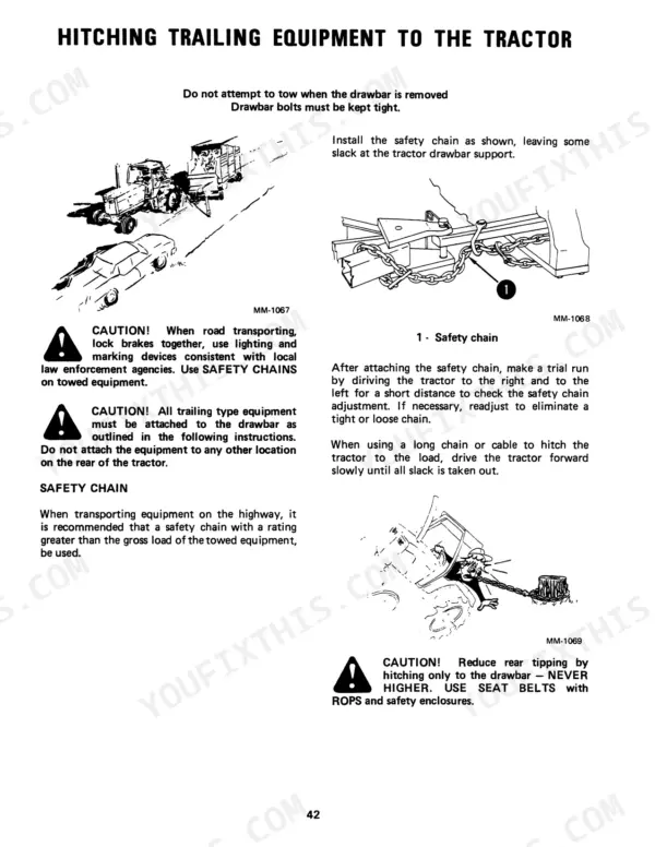
| Hitching Trailing Equipment to the Tractor | 46-47 | Safety Chain, Power Take-Off Shaft, Drawbar, PTO Shaft Dia., Maximum Static Drawbar Vertical Load |
| All-Wheel Drive/ Differential Lock | 49 | Front Axle Assembly, Traction, Shifter Lever, Clutch Pedal, Differential Lock, Operating Pedal |
| Front Wheels | 50-52 | Toe-In, Wheel Bolts, Tie Rod End Nuts, Adjustable Front Axle, Front Tread, Drag Link |
| Rear Wheels | 53 | Pressed Steel Rear Wheels, Rear Tread Width, Reversing the Rear Wheels, Wheel Bolts, Tightening Torque, Cast Iron Wheel Weights |
Quick Reference Specifications
| Specification | Value | Page |
|---|---|---|
| Hydraulic system capacity | 22.2 qts. (21L) | p. 64 |
| Minimum antifreeze percentage | 33 percent | p. 33 |
| Engine Oil Capacity (with filter change) | 4.8 qts (4.5L) | p. 64 |
| Front Wheel Toe-in | 1/4-inch (6.4 mm) ±1/16-inch (1.5mm) | p. 50 |
| Rear Wheel Bolt Torque | 81 to 97 ft-lbs (118-131 N-m) | p. 53 |
| ROPS Mounting Bolt Torque | 80 ft. lbs. (108.5 N-m) | p. 11 |
| Maximum Static Drawbar Vertical Load | 300 lbs (136 kg) | p. 47 |