


Part of the Case IH Operator Manuals.
This 170-page Case IH 245, 255 Operator Manual (OEM #9-12471) puts the factory operating procedures for both agricultural tractor variants on your screen. You get a thorough safety section with pre-start rules, operation warnings, and service decals, followed by instrument guides for your tachometer, fuel gauge, glow plug indicator, and charge warning light, plus separate travel speed charts for the 245 and 255 across every gear-and-range combination. Inside: a full maintenance schedule covering engine oil selection by ambient temperature, transmission hydraulic filter service intervals, cooling system thermostat and fan belt procedures, and step-by-step fuel system service. Set the neutral safety switch stroke to 0.16–0.20 inch (4–5 mm) before the first key turn. No more hunting through a paper manual in the cab. Bookmarked by section and keyword-searchable, this PDF opens on any device and goes where you go.
What's Inside This Case IH 245, 255 Operator Manual
| System | Pages | Key Topics |
|---|---|---|
| Machine Identification | 3-4 | To the Owner of a Case Ih Tractor, Tractor Model Number, Product Identification Number, Engine Serial Number, Transmission Serial Number, ROPS Serial Number |
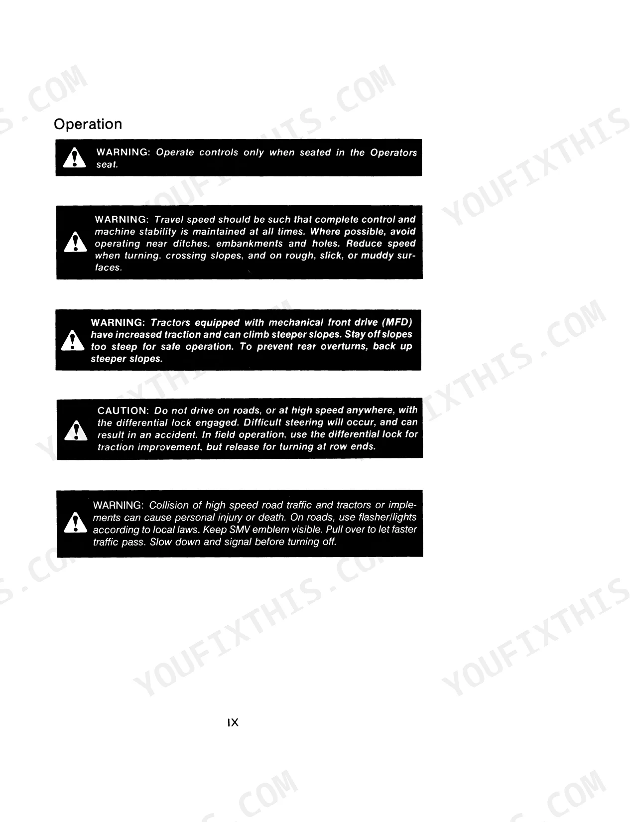
| Safety & Hand Signals | 7-16 | Start the Engine, Stop the Engine, Move Out, Come to Me, Raise Equipment, Lower Equipment |
| Specifications | 17-38 | Crankshaft, Piston and Rod, Engine Lubrication System, Cooling System, Electrical System, Transmission, Clutch, Tire Inflation Specifications, Tire Load Capacity, Front Wheel Tread Positions, Rear Wheel Tread Positions, Diesel Fuel Specifications |
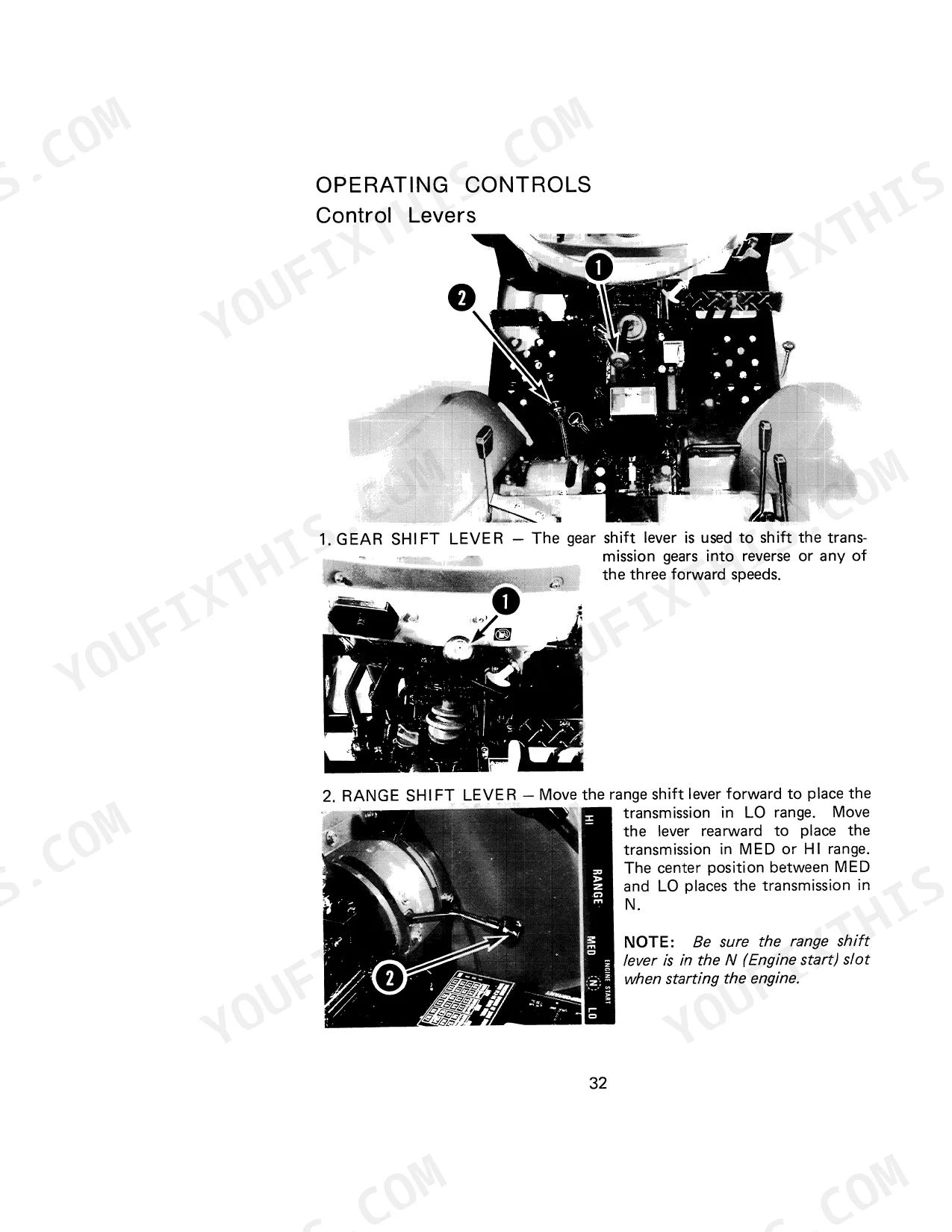
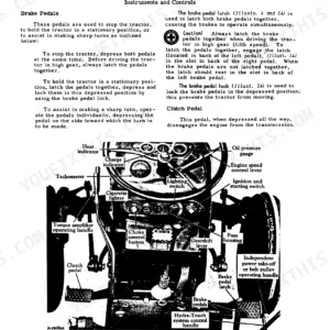
| Instruments & Operating Controls | 39-58 | Tachometer and Hourmeter, Fuel Gauge, Engine Glow Plug Indicator, Turn Signal Indicators, Charge Indicator, Engine Oil Pressure Indicator, Starter Key Switch, Engine Speed Control Lever, Throttle Pedal, Brake Pedals, Clutch Pedal, Gear Shift Lever |
| Starting & Operating Procedures | 59-70 | Run-In Procedure, Engine Oil Level Check, Transmission Fluid Level Check, Cooling System Check, Tire Pressure Check, Fuel Shut-Off Valve, PTO Control Lever, Range Shift Lever, Cold Temperature Operation, Coolant Heater, Seat Belt |
| Roll Over Protective Structure (ROPS) | 71-80 | Foldable ROPS Frame, Normal Operating Position, Low Clearance Positions, Folding the ROPS, Securing the ROPS in the Upright Position, ROPS Label |
| Drivetrain, MFD & PTO Controls | 81-89 | Transmission Operation, Gear Shift Lever, Range Shift Lever, MFD Front Axle, MFD Control Lever, Differential Lock, Rear PTO, Mid PTO, Live PTO, PTO Output Shaft Speed, Power Takeoff Guards, PTO Operating Safety |
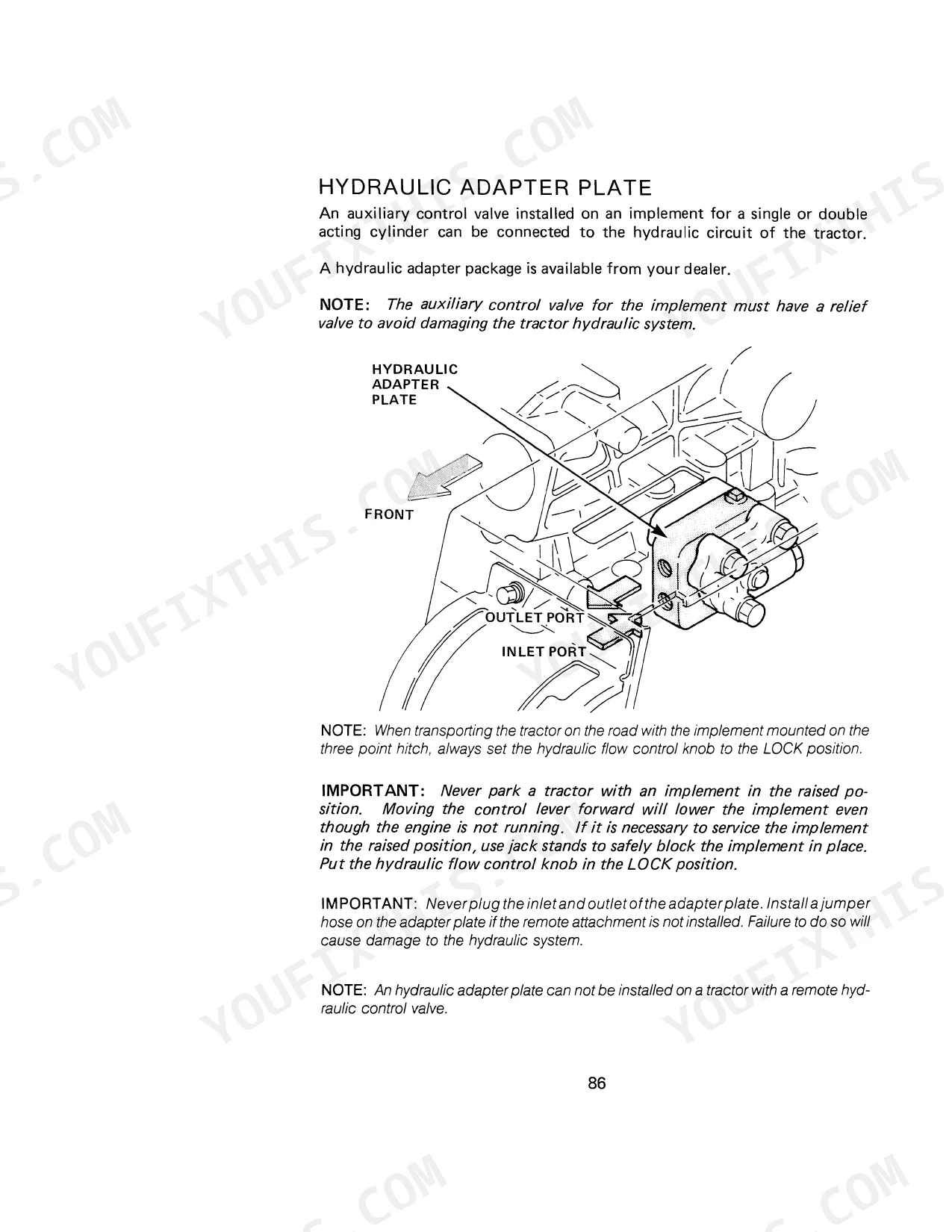
| Hitch, Drawbar & Remote Hydraulics | 90-103 | Drawbar, Implement Hitch, Safety Chain, Three Point Hitch System, Upper Link, Lift Links, Hitch Control Lever, Draft Control Lever, Remote Hydraulic Control Valve, Hydraulic Adapter Plate, Auxiliary Control Valve |
| Wheel Adjustments & Ballast | 104-115 | Non-Adjustable Front Axle, Adjustable Front Axle, Drag Link Adjustment, Toe-In Adjustment, Front End Weights, Rear Wheel Weights, Tire Liquid Weight |
| Lubrication & Wheel/Tire Service | 116-132 | Service Point Table, Lubrication Points, Engine Oil Level, Engine Oil Change, Engine Oil Filter, Transmission Oil Level, Transmission Oil Change, Hydraulic Filter Screen, Front Wheel Bearing Lubrication, Tire Pressure Check Interval, Tire Installation |
| Cooling, Fuel & Clutch Service | 133-150 | Pressure Cooling System, Thermostat Check, Fan Belt Adjustment, Fuel Filter Element, Fuel Injection Pump, Nozzle Check, Air Induction System, Filter Element, Clutch Pedal Adjustment, Clutch Rod |
| Electrical System & Battery | 151-162 | Neutral Start Switch, Head Lamps, Turn Signal and Flasher Lamp, Fuses, Head Lamp Adjustment, Battery Cables and Terminals, Removal and Installation of Battery, When Charging the Battery |
| Storage & Reference | 163-170 | ROPS Inspection and Maintenance, Seat Belt Inspection and Maintenance, Tire Cleaning, Fuel Tank Filling, Battery, Clutch Lock Latch, Radiator Coolant Level, Starting the Engine |
Quick Reference Specifications
| Specification | Value | Page |
|---|---|---|
| Neutral Safety Switch Stroke Adjustment | 0.16 to 0.20 inch (4 to 5mm) | p. 151 |
Case IH 245, 255 Common Problems This Manual Covers
Case IH 255 tractor won't start despite dashboard lights working and starter clicking repeatedly.
Inspect the neutral start switch on page 151. Verify the range shift and PTO control levers are fully disengaged. Adjust the lock nuts of each switch to achieve a 0.16 to 0.20 inch (4 to 5mm) stroke when pushed by the lever.
Manual Section: Neutral Start Switch p. 151Engine cranks slowly and fails to fire during extreme cold temperature operation.
Drain water from the fuel filter cup and bleed the fuel system. Fill the tank with acceptable Number Two Diesel Fuel as specified on page 38. Review the cold temperature operation procedures on page 67 to properly warm the engine oil before applying a load.
Manual Section: Cold Temperature Operation p. 67Rear implement driveshaft grinds or fails to engage when moving the selector lever.
Depress the clutch pedal completely to halt the transmission. Shift the PTO selector lever into Position 1 as outlined on page 87. Check the clutch rod and jam nut on page 148 to adjust the free pedal movement if the gears continue grinding during engagement.
Manual Section: Live PTO p. 87Frequently Asked Questions
How to reset neutral safety switch on Case IH 245 compact tractor?
To adjust the neutral start switch, first disconnect the switch terminals. Then, loosen the lock nuts and turn the switch counter-clockwise to remove it. If replacing, install a new switch and adjust the lock nuts to achieve a stroke of 0.16 to 0.20 inch (4 to 5mm) when the switch is pushed by the range shift lever or PTO control lever. p. 151
How will I receive this Case IH 245, 255 Operator Manual?
A 170-page Operator Manual in searchable PDF format, available the moment you complete checkout. View on computer, tablet, or phone, with no shipping wait.
Is this Case IH 245
Yes. The PDF has no DRM restrictions, so print any page or section you need for your shop. Works with any standard printer.


Reviews
There are no reviews yet.