


Part of the Case IH Operator Manuals.
Need the factory operator guide for your Case IH 3230? This 267-page 3200 and 4200 Series Operator Manual (OEM #Don 9-24854) covers the 3220, 3230, 4210, 4230, and 4240 tractors. Inside: wiring diagrams for the electrical system, hydraulic schematics for your remote circuits and three-point hitch, and tire pressure and load capacity tables for every wheel configuration. You also get a Lubrication/Maintenance Chart with service intervals, complete fluid capacities, a full safety section covering ROPS requirements and cab decals, and Digital Instrument Cluster programming procedures. Set the radiator cap to 9-12 psi (0.62-0.82 bar), torque rear wheel mounting nuts to 205-220 lb ft (278-298 Nm), and service the transmission/hydraulic filter every 200 hours. No more hunting for service intervals in forum threads. Bookmarked and searchable: pull it up on your tablet at the machine and get back to work.
What's Inside This Case IH 3220-4240 Series Operator Manual
| System | Pages | Key Topics |
|---|---|---|
| To the Owner | 8-10 | - |
| Indentification Numbers | 11-13 | - |
| Safety/Decals | 14-25 | Safety Rules, Mounting and Dismounting the Tractor, Safety Decals, Roll Over Protective Structure |
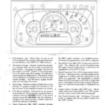
| Instruments/Controls | 26-52 | Digital Instrument Cluster, Operating Controls, Rear View Mirrors, Roof Hatch, Rear Window, Cab Door Lock, Operators Seat |
| Operating Instructions | 53-95 | Before Starting the Engine, Service Indicator Lamps and Gauges, Run in Procedure, Seat Belt, Normal Starting Procedure, Stopping the Engine, Parking the Tractor |
| Field Operation | 96-131 | Drawbar Preparation, Three Point Hitch System Preparation, Three Point Hitch Operation, Remote Hydraulics Operation, Auxiliary Power Connections |
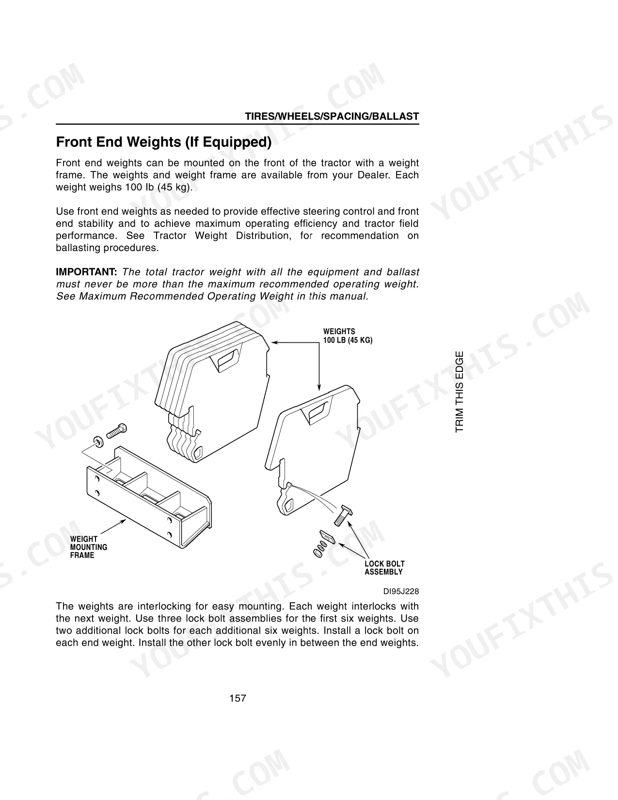
| Tires/Wheels/Spacing/Ballast | 132-168 | Tire and Wheel Equipment, Tire Pressures and Load Capacities, Tire and Wheel Service, Front to Rear Tire Size Combinations, Front Wheel Tread Positions, Rear Wheel Tread Positions |
| Lubrication/Filters/Fluids | 169-206 | Hourmeter, Systemgard Lubrication Analysis Program, Lubrication/Maintenance Chart, Hood and Side Covers, Grease Points, Capacities, Engine Lubrication, Fuel System |
| Maintenance/Adjustments | 207-225 | Cooling System, Fan/Alternator Belt and Compressor Belt, Operators Cab, Brakes, Engine Clutch, Valve Clearences |
| Electrical System | 226-241 | Fuses, Battery, Bulb and Lamp Replacement |
| Machine Storage | 242-243 | Engine Crankcase, Oil Filter, Fuel Filter, Cooling System, Battery, Tires |
| Specifications | 244-261 | Diesel Engine, Travel Speeds, Speed Chart Adjustment for Alternative Tires, Approximate Tractor Measurements, Approximate Tractor Weights |
Quick Reference Specifications
| Specification | Value | Page |
|---|---|---|
| Rear Wheel Mounting Bolt Torque | 205 to 220 lb ft (278 to 298 Nm) | p. 147 |
| Rear Wheel Rim Bolt Torque | 155 to 199 lb ft (210 to 270 Nm) | p. 147 |
| Transmission/Hydraulic Oil Filter Change | After first 20 hours of operation then every 200 hours | p. 193 |
| Differential Oil Change (MFD) | After first 20 hours of operation then every 800 hours | p. 195 |
| Radiator Cap Pressure | 9 to 12 psi (0.62 to 0.82 bar) | p. 182 |
Case IH 3220-4240 Series Common Problems This Manual Covers
Case IH 3200/4200 Series engine warning light flashing on instrument cluster at startup
Check the service indicator lamps section starting on page 53. Verify engine oil level is at the FULL mark on the dipstick before each shift. Inspect the instrument cluster gauges for oil pressure or temperature readings outside normal range. If the lamp persists after the engine warms, check all fluid levels and inspect sensor connectors for corrosion or loose pins.
Manual Section: Operating Instructions p. 53Engine hard to start or cranks slowly in cold morning conditions
Review the Normal Starting Procedure on page 53 before attempting a restart. Verify battery terminals are clean and tight. Check that fuel is appropriate for current ambient temperature. Follow the cold-start glow plug warm-up sequence exactly as described. If cranking remains weak, inspect battery condition and charge level before calling for service.
Manual Section: Operating Instructions p. 53Transmission shifting feels sluggish or jerky after recent service
Verify the hydraulic oil filter was changed at the correct interval: after the first 20 hours of operation, then every 200 hours (page 193). Check transmission oil level using the sight glass or dipstick per the lubrication chart. Confirm the correct oil type and quantity were used at the last service. Air in the hydraulic circuit after a filter change can cause sluggish response for a short period during initial operation.
Manual Section: Lubrication/Filters/Fluids p. 193Coolant temperature gauge reading high or steam visible from hood area
Let the engine cool completely before opening the cooling system. Inspect the radiator cap: the correct pressure rating is 9 to 12 psi (0.62 to 0.82 bar), as shown on page 182. Check coolant level in the overflow tank and radiator. Inspect hoses for cracks or loose clamps. Verify coolant has been changed on schedule: every 2000 hours or every 2 years, per page 182. Clean debris from the radiator exterior fins with compressed air.
Manual Section: Lubrication/Filters/Fluids p. 182Brake pedals uneven or tractor pulling to one side during braking
Inspect brake pedal alignment and free travel before operating on a road. The brake pedal adjustment procedure is on pages 208 to 211. Park on level ground, chock the wheels, and compare pedal height and travel side to side. Uneven engagement is a safety risk during transport. Do not operate at road speeds until pedals are equalized.
Manual Section: Maintenance/Adjustments p. 208Air filter restriction indicator light on, engine losing power under load
Service the air filter immediately when the restriction indicator activates. Remove and inspect the primary filter element per the procedure on pages 189 to 190. Tap the element gently to dislodge loose dust, or replace if damaged or heavily loaded. Inspect the secondary safety element: replace it, never clean it. Verify all air intake clamps and ducts are sealed tight before restarting.
Manual Section: Lubrication/Filters/Fluids p. 189Frequently Asked Questions
How to reset maintenance indicator on Case IH 3230?
To reset the maintenance indicator, which is the service hours timer on the digital instrument cluster, first enter the programming mode as described on page 112. Then, select Code Number 3 on the upper digital display. Use the PTO rpm touch button to increase the number or the ENGINE rpm touch button to decrease it, setting the timer to 0 hours. Press and hold both the ENGINE rpm and PTO rpm touch buttons for two or more seconds to save the 0 hours setting, effectively disabling the timer. Exit the program by turning the keyswitch to the OFF position. p. 121
What do the service indicator lamps mean on the Case IH 3200 or 4200 Series instrument cluster?
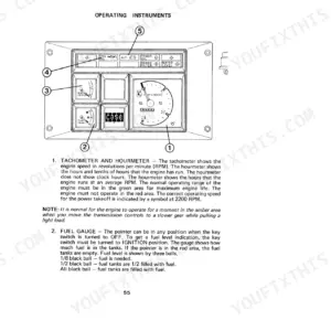
The service indicator lamps on the digital instrument cluster (covered starting on page 53) warn of low oil pressure, high coolant temperature, or other system conditions requiring attention. Before each shift, verify engine oil level is at the FULL mark on the dipstick. If a lamp activates during operation, check the instrument cluster gauges for abnormal oil pressure or temperature readings. If the lamp persists after the engine warms up, check all fluid levels and inspect sensor connectors for corrosion or loose pins before continuing work. p. 53
How do you start a Case IH 3230 in cold weather?
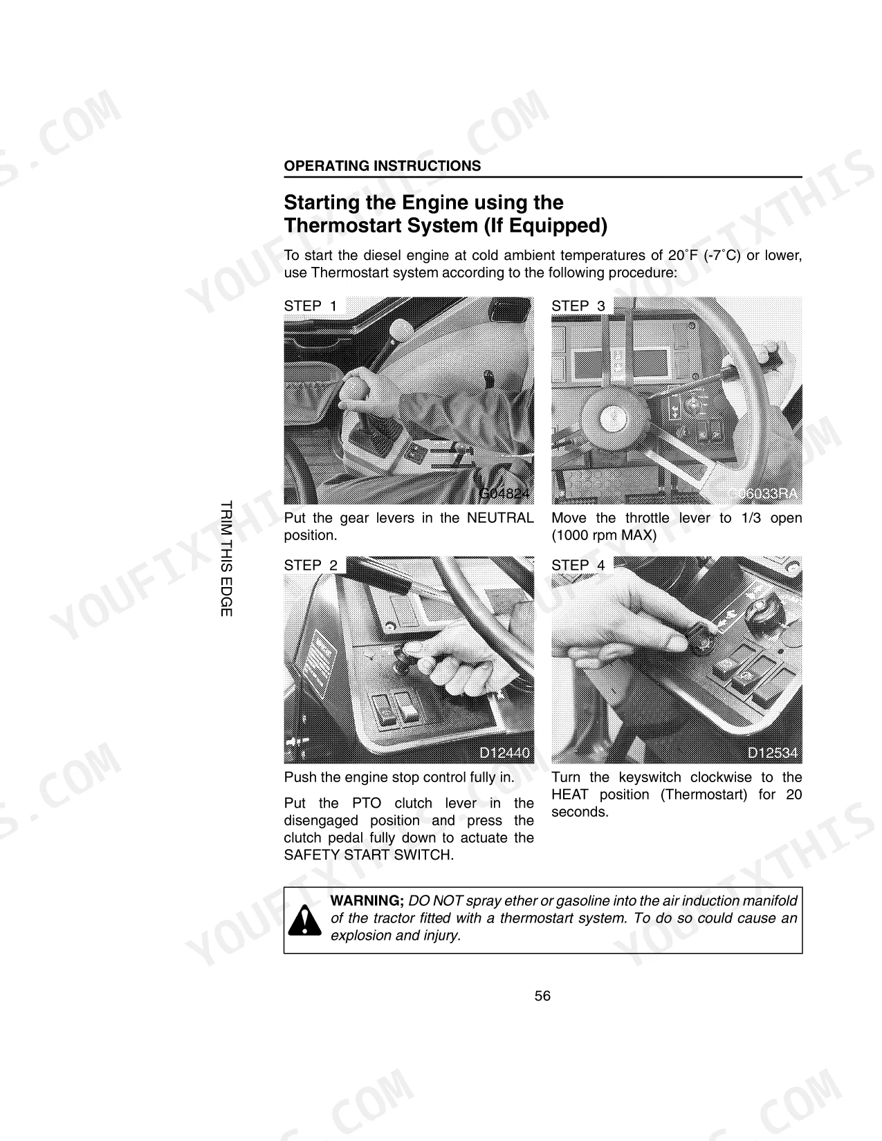
Follow the cold-start glow plug warm-up sequence in the Normal Starting Procedure on page 53. Confirm battery terminals are clean and tight and that fuel is appropriate for the current ambient temperature. Allow the glow plugs to complete their warm-up cycle before cranking. If cranking remains weak after following the procedure, inspect the battery condition and charge level before calling for service. p. 53
Why does the Case IH 3200 Series transmission shift sluggishly after a hydraulic filter change?
Air in the hydraulic circuit after a filter change can cause sluggish or jerky shifting for a short period during initial operation. Verify the hydraulic oil filter was replaced at the correct interval: after the first 20 hours of operation, then every 200 hours (page 193). Check the transmission oil level using the sight glass or dipstick per the lubrication chart and confirm the correct oil type and quantity were used at the last service. p. 193
Is this Case IH 3220, 3230, 4210, 4230, 4240, 3200 Series Tractors, 4200?
You get a 267-page searchable PDF (38 MB) that downloads instantly after checkout. Open it on your laptop, tablet, or phone, and bring it right to the shop floor.
Am I able to print pages from this Case IH 3220, 3230, 4210, 4230, 4240, 3200?
No restrictions at all. Print individual pages, full chapters, or the entire manual. The PDF is completely unlocked.
Are hydraulic system diagrams in this Case IH 3220, 3230, 4210, 4230, 4240?
Yes. The manual includes a hydraulic system diagram covering the main circuits.


Reviews
There are no reviews yet.