


Part of the Case IH Repair Manuals.
All 764 pages of this Case IH DX31, DX34 Repair Manual (OEM #87535066) are built around one job: getting your DX31 or DX34 tractor back to factory condition. Inside, you get full wiring diagrams covering the battery, key switch, relays, alternator, and safety start circuit, plus hydraulic schematics tracing every valve, pump, and lift cylinder through the system. A thorough troubleshooting section and page after page of torque specs cover everything from the engine block to the hydrostatic transmission. Replace the clutch disc when it drops below 7.2 mm (down from the 3.2 mm factory spec), and torque the hydraulic pump cover bolts to 22–28 N·m. Your machine is down. Pull up this bookmarked PDF on any device, search the spec you need, and get back to wrenching.
What's Inside This Case IH DX31, DX34 Repair Manual
| System | Pages | Key Topics |
|---|---|---|
| General Information | 39-66 | Precautionary Statements, Personal Safety, Machine Safety, Information, Safety (Precautionary Statements, Tractor, Servicing the Tractor) |
| Engine | 67-188 | Engine Bolt Torque Specifications, Cylinder Head and Valve Train Components, Cylinder Block Assembly, Fuel Injector and Glow Plug, Oil Pump, Cooling System |
| Clutch | 189-210 | Single Clutch, HST Transmission, Double Clutch, PTO Clutch, Clutch Pilot Bearing, Clutch Release Bearing |
| Gear Transmission | 211-258 | Powerflow, Initial Power Flow -- Transmission Input, Initial Power Flow -- PTO Input, FWD Power Flow, Shift Rails, Transmission Differential |
| FWD Axle | 259-282 | Front to Rear Axle Ratio, Front Axle and Differential, Drive Pinion, Differential Gear, Reduction Gear -- Drop Box, Steering Stops |
| Differential, Rear Axle | 283-306 | Differential Assembly, Differential Lock, Drive Pinion, Rear Axle, Ring Gear and Pinion Gear Pattern Specification and Adjustment |
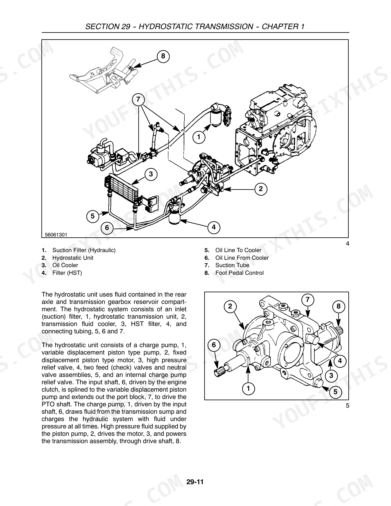
| Hydrostatic Transmission | 307-380 | Variable Displacement Pump, Fixed Displacement Motor, HST Charge Circuit, Hydrostatic Gearbox, Port Block -- Neutral and Feed Valves, High Pressure Relief Valve |
| Power Take-Off Systems | 381-398 | Live Power Take-Off, Power Take-Off Drive -- Hydrostatic Transmission, Output Shaft, Rear Countershaft, Front Countershaft, Mid-Mount Power Take-Off |
| Brakes | 399-410 | Parking Brake, Overhaul, Brake Adjustment |
| Hydraulic System | 411-466 | Hydraulic Pump, Hydraulic Fluid Filter, Combination System Relief - Diverter Valve Manifold, Control Valve (Hpl), Lift Cylinder, Remote Valves |
| Steering Systems | 467-514 | Power-Steering Control Motor, Power Steering Pump, FWD Steering Cylinder, Steering Column, Steering Stops |
| Wheels and Tires | 515-522 | FWD Tread Setting, Rear Axle Tread Setting, Tractor Weighting, Rear Wheel Weight Installation, Liquid Ballast, Tire Pressure |
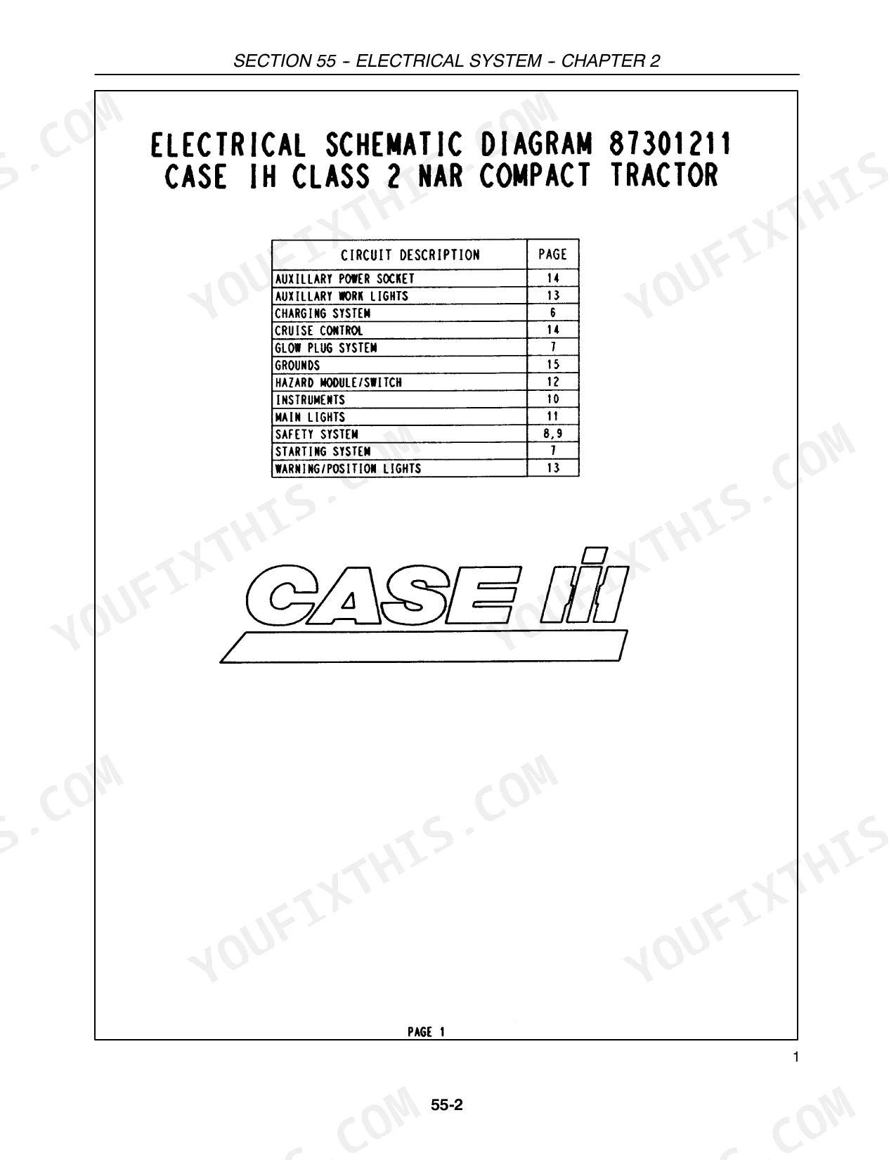
| Electrical System | 523-738 | Battery and Fuses, Key Switch, Relays, Alternator, Starter Motor, Safety Start Circuit |
| Platform | 739-764 | Hood, Dash Console, Seat, ROPS, Fenders, PTO and Range Controls |
Quick Reference Specifications
| Specification | Value | Page |
|---|---|---|
| Hydraulic pump service parts | Only shaft seal and internal O rings are serviceable. If troubleshooting indicates a faulty pump, replace the pump with a new assembly. | p. 447 |
| Hydraulic pump cover retaining bolts torque | 22 – 28 N⋅m (16 – 20 ft. lbs.) | p. 448 |
| Clutch Disc Thickness | 8.0 mm (0.315″) | p. 192 |
| Clutch Disc Thickness Allowable Limit | 7.2 mm (0.28″) | p. 192 |
| Oil filter replacement interval | Every 100 hours of operation | p. 132 |
| Lift Cylinder Diameter | 70 mm (2.76″) | p. 414 |
| Piston-to-Tube Clearance | 0.7 mm (0.027 in.) max. | p. 469 |
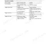
| Troubleshooting: Implement fails to lift when lever is in raised position (Possible Causes & Remedies) | Possible Causes: Linkage out of adjustment, Relief valve setting too low, Faulty safety valve, O ring failure on control valve body to cover, Excessive fluid leakage past lift cylinder piston seal, Restricted suction filter, Unload valve does not close, Lowering valve remains open. Remedies: Adjust external and internal linkage, Perform system relief valve pressure test, Repair or replace safety valve, Repair as required, Replace seal, piston, or cylinder as required, Clean or replace as required, Check unload valve operation, Check lowering valve adjustment and operation. | p. 428 |
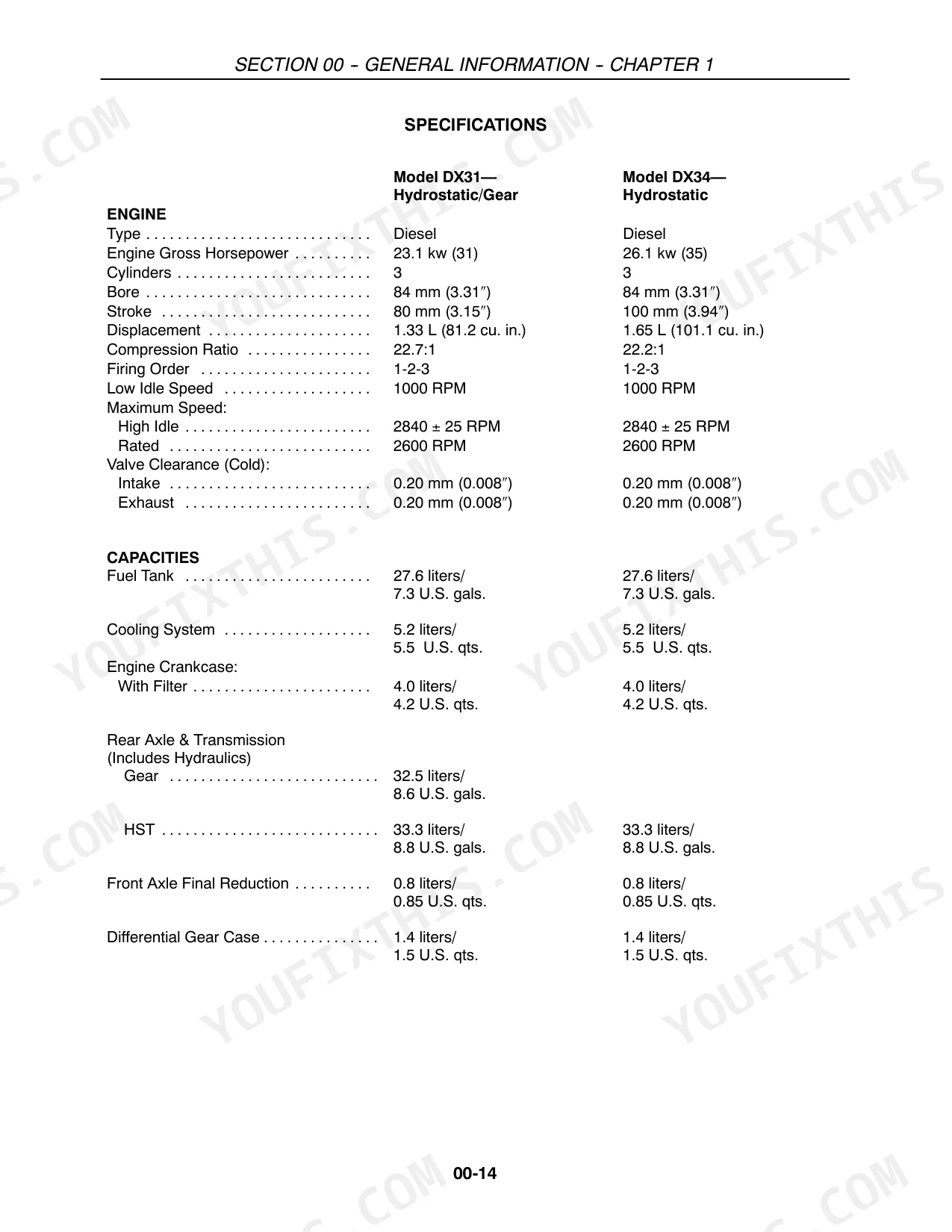
| Fuel Tank Capacity | 27.6 liters/7.3 U.S. gals. | p. 52 |
| Engine Crankcase Capacity (With Filter) | 4.0 liters/4.2 U.S. qts. | p. 52 |
| Radiator Cap Pressure | 0.9 bar (13 PSI) | p. 79 |
| Clutch Pedal Free-Travel | 19 -- 30 mm (3/4 -- 1-3/16″) | p. 81 |
Case IH DX31, DX34 Common Problems This Manual Covers
Case IH DX31 implement fails to lift when lever is raised or holds load poorly.
Check the system relief valve pressure test on page 428. Verify the relief valve setting reaches 147 ± 5 bar (2133 ± 70 psi) as specified on page 414. If pressure is low, inspect the lift cylinder piston seal for excessive fluid leakage and replace if damaged.
Manual Section: Hydraulic System Troubleshooting p. 428Tractor transmission slips under heavy load and loses forward motion during field operation.
Measure the clutch disc thickness as detailed on page 192. Replace the disc if it wears below the 7.2 mm (0.28 inch) allowable limit. When installing the new assembly, torque the clutch mounting bolts to 22.6 to 28.4 N⋅m (16.6 to 21 ft. lbs.) per page 470.
Manual Section: Clutch p. 192Engine loses power abruptly during operation and fails to restart while in the field.
Test the fuel injection pump pressure to ensure it reaches 147 bar (2150 psi) as shown on page 151. Drain and inspect the fuel system for blockages if pressure drops. Replace the engine oil filter every 100 hours of operation per page 132 to maintain optimal performance.
Manual Section: Engine p. 151Hydraulic pump emits abnormal noise and fluid leaks from the cover retaining bolts.
Inspect the hydraulic pump internal O rings and shaft seal for damage. Replace the entire pump assembly if internal components fail, as noted on page 447. Torque the cover retaining bolts to 22 to 28 N⋅m (16 to 20 ft. lbs.) on page 448 during reassembly.
Manual Section: Hydraulic System p. 447Frequently Asked Questions
What are the torque specs for the engine bolts on Case IH DX34?
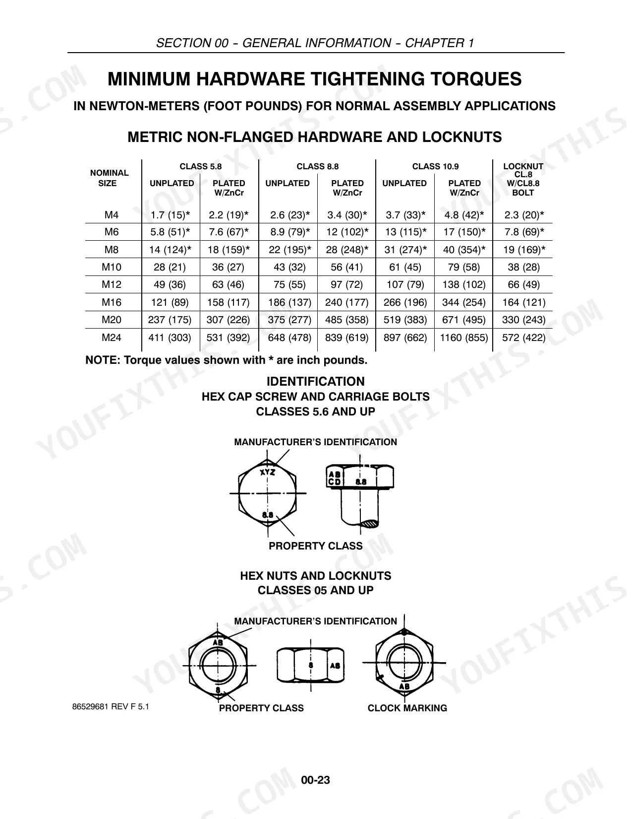
The engine bolt torque specifications for the Case IH DX34 are listed in Section 10 - ENGINE. For instance, the Cylinder head Bolt should be torqued to 98 - 103 N⋅m (72 - 76 ft. lbs.), and Flywheel Retaining Bolts to 69 - 78 N⋅m (51 - 58 ft. lbs.). p. 80
How to interpret error codes on Case IH DX31 and DX34?
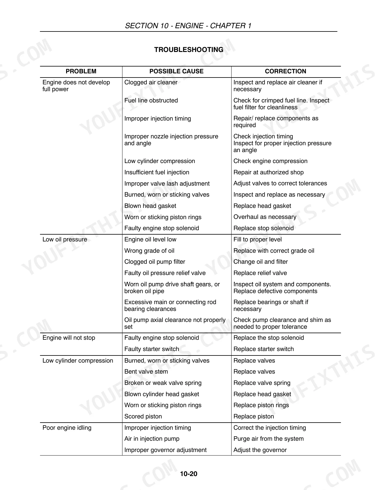
The manual does not provide a section for interpreting generic "error codes." Instead, it offers detailed "TROUBLESHOOTING" tables for various systems (e.g., Engine, Electrical System) that list specific "PROBLEM" symptoms, their "POSSIBLE CAUSE," and recommended "REMEDY" actions. p. 86
What are the replacement specifications for Fuel pump?
The replacement specifications for the fuel pump (Injection Pump) for both Case IH DX31 and DX34 models indicate the manufacturer assembly number is Bosch 104135 -- 3061. p. 151
What are the replacement specifications for Hydraulic pump seals?
For the hydraulic pump, the only serviceable parts are the shaft seal and internal O-rings. If troubleshooting indicates a faulty pump, the entire pump assembly should be replaced, as no specific replacement specifications for individual seals are provided. p. 447
Is this Case IH DX31, DX34 Repair Manual a digital download?
Instant PDF download. You get the full 764-page searchable Repair Manual immediately after payment. Open it on your laptop, tablet, or phone right in the shop.
Can I print specific sections of this Case IH DX31, DX34 Repair Manual?
No restrictions at all. Print individual pages, full chapters, or the entire manual. The PDF is completely unlocked.
Does this Case IH DX31, DX34 Repair Manual cover the hydraulic system?
Yes, this Case IH DX31, DX34 Repair Manual includes hydraulic system diagrams, circuit schematics, and component specifications.


Reviews
There are no reviews yet.