


Part of the Case IH Repair Manuals.
Need the factory service data for your Cross-Flow CF 80? All 552 pages of this combine harvester service manual span the CF 80, 70, 60, and 50, from engine and fuel injection through the threshing unit, cleaning unit, and grain tank. You get complete circuit diagrams for each model variant, hydraulic schematics covering the axial reciprocating pump, distributing valves, and header circuits, plus an electrical chapter mapping the central processing unit, Design P and Q field tracking systems, relay equipment, and connector pinouts. Torque tables cover the front axle, crosshead, straddle gear, and gearbox, with troubleshooting charts for the hydrostatic ground drive and straw chopper. Drain the water separator every 50 hours, swap engine oil at 240 operating hours, and confirm the reflux filter bypass opens at 3.5 bar absolute. Your combine doesn't wait for weather. Bookmarked by chapter and keyword-searchable: grab your tablet and walk to the machine.
What's Inside This Case IH CROSS-FLOW CF 80 Manual
| System | Pages | Key Topics |
|---|---|---|
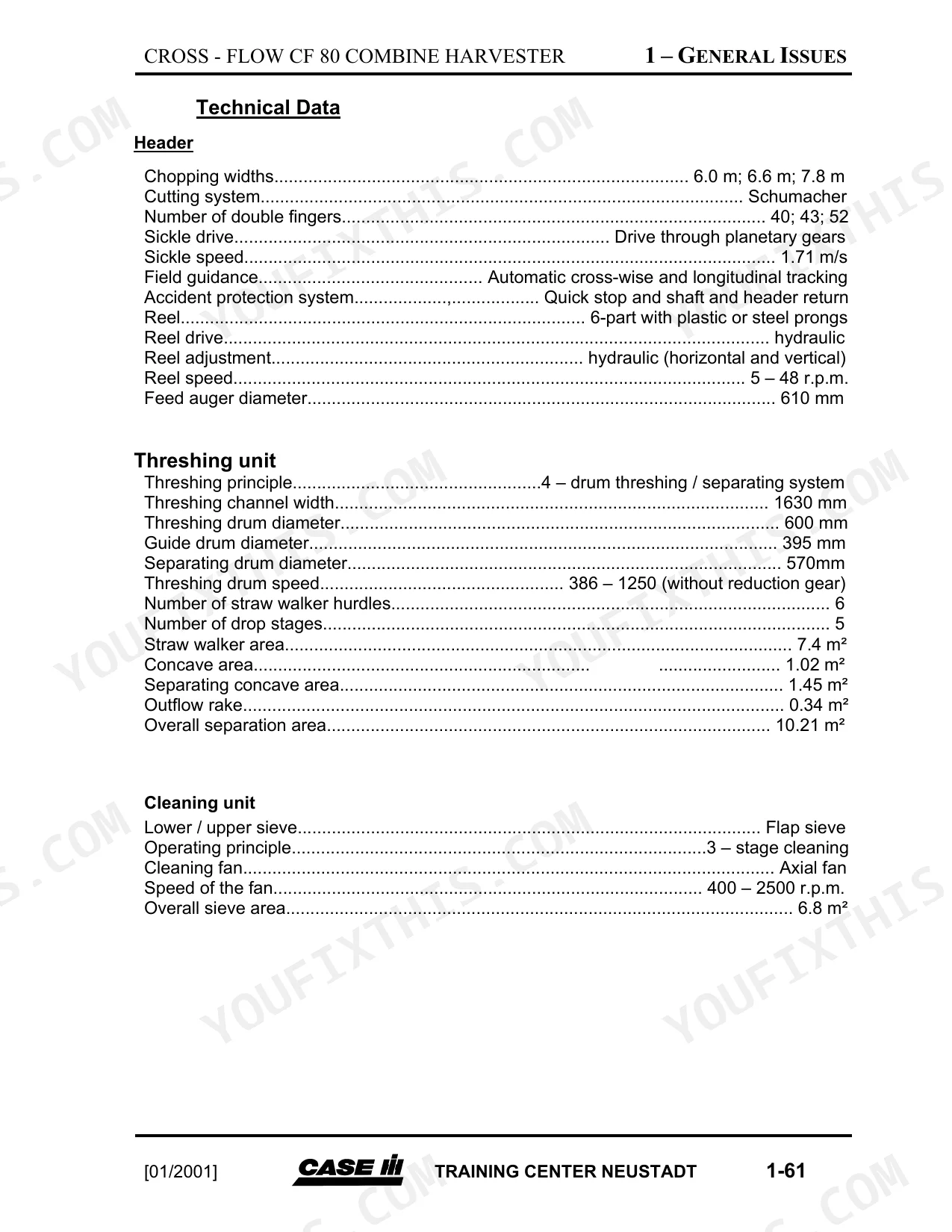
| Machine Overview & Specifications | - | Functional Elements, Equipment and Accessory Equipment, Dimensions, Delivery Inspection, Lubrication Schedule, Technical Data |
| Engine & Fuel System | - | Lubrication of Engine, Engine Oil Level, Engine Oil Change, Oil Viscosity/Temperature Ranges, Cooling System Maintenance Intervals, Fuel Tank, Fuel Filter, Water Separator Filter, Fuel System Bleeding, Injection Nozzles |
| Cab Controls & Starting | - | Fan Speed Switch, Warning Beacon Switch, Heating and Ventilation, Reel Control Switch, Header Lift Switch, Unloading Auger Switch, Electronic Start Safety System, Tell-Tale Lamps, Starting Procedure, Ignition Sequence, Engine Stop Solenoid, Hooter Signal |
| Header Return & Field Tracking Systems | - | Reel Speed Control, Threshing Cylinder Speed, Header Reverse Switch, Operating Display Device, Header and Feeder Reverser, Automatic Shutoff, Clogging Clearance, Manual Program, High-Cut Program, Field Tracking Program, Setting the Angle Transmitter, Support Pressure Control Program |
| Instrument Displays & Lighting | - | Cooling Water Temperature, Fuel Display, Engine Oil Pressure, Filling Level Transmitter, Straw Area Clogging, LCD Screen, Function Keys, Loss Transmitter, Headlight Setting, Low Beam, Asymmetric Headlights, Bright-Dark Boundary |
| Electrical Components & Protection | - | Proportional Amplifier, Card Subassembly Start Stop, Card Subassembly Field Tracking, Card Subassembly Header Return, Control Unit, Safety Relay, Chaff-Cutter Clutch Relay, Main Fuse, Working Hydraulics Fuse, Lighting System Fuse |
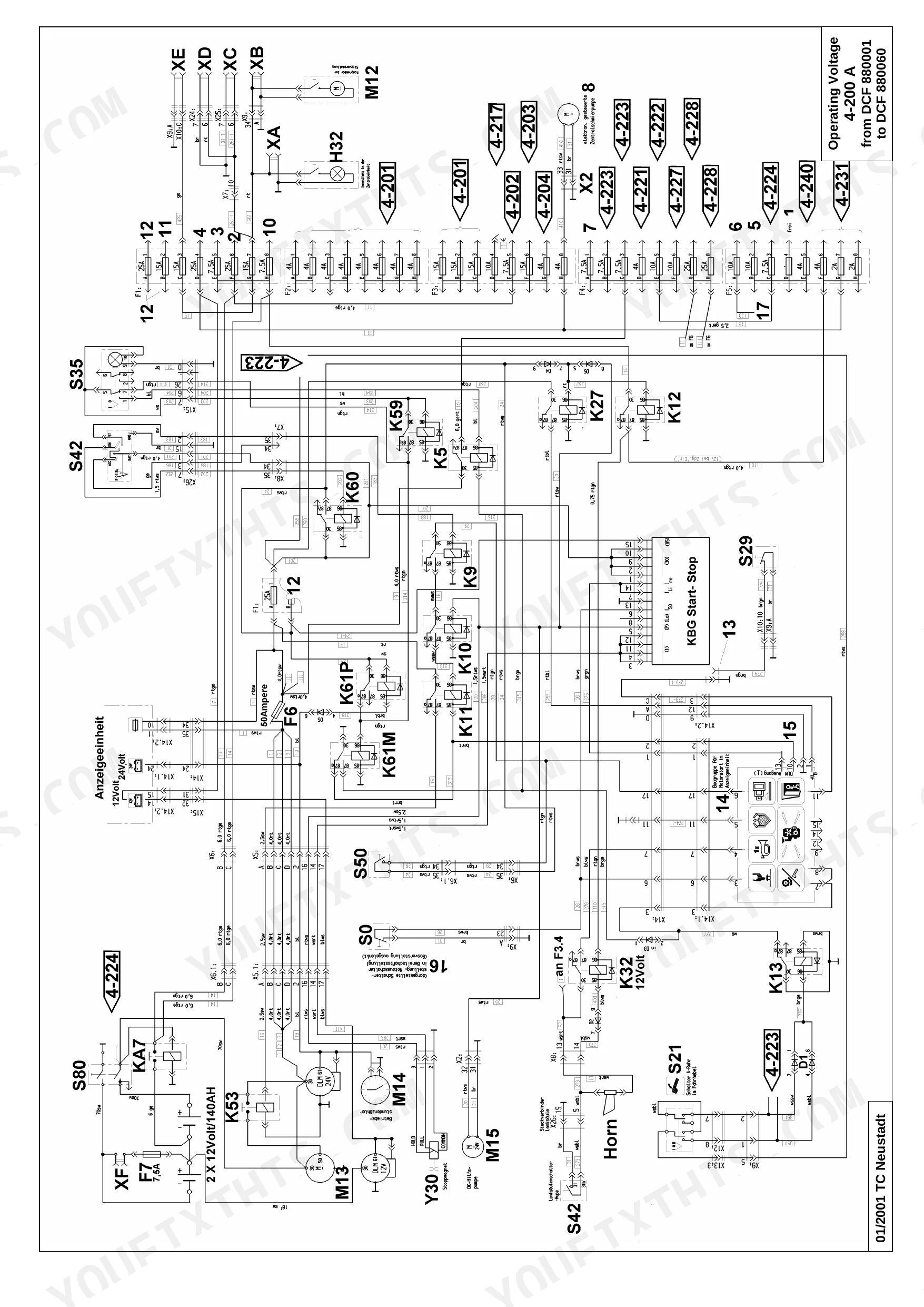
| Wiring Diagrams & Circuit Schematics | - | Header Connectors, Control Panel Connectors, Cab Roof Connectors, Electronics Subassembly Connectors, Cable Colors, Cable Cross-Section, Contact Mechanism Relays, Operating Voltage, Warning Device, Direction Indicator, Mirror Adjustment, Cf 60 Series Wiring |
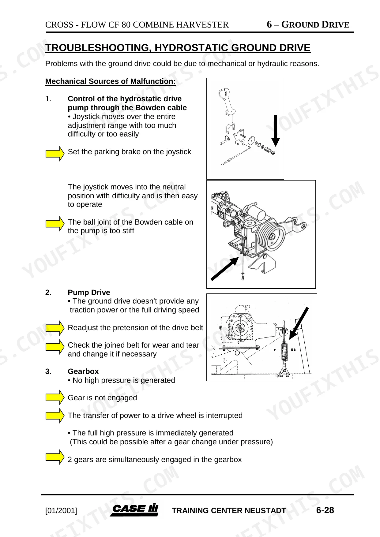
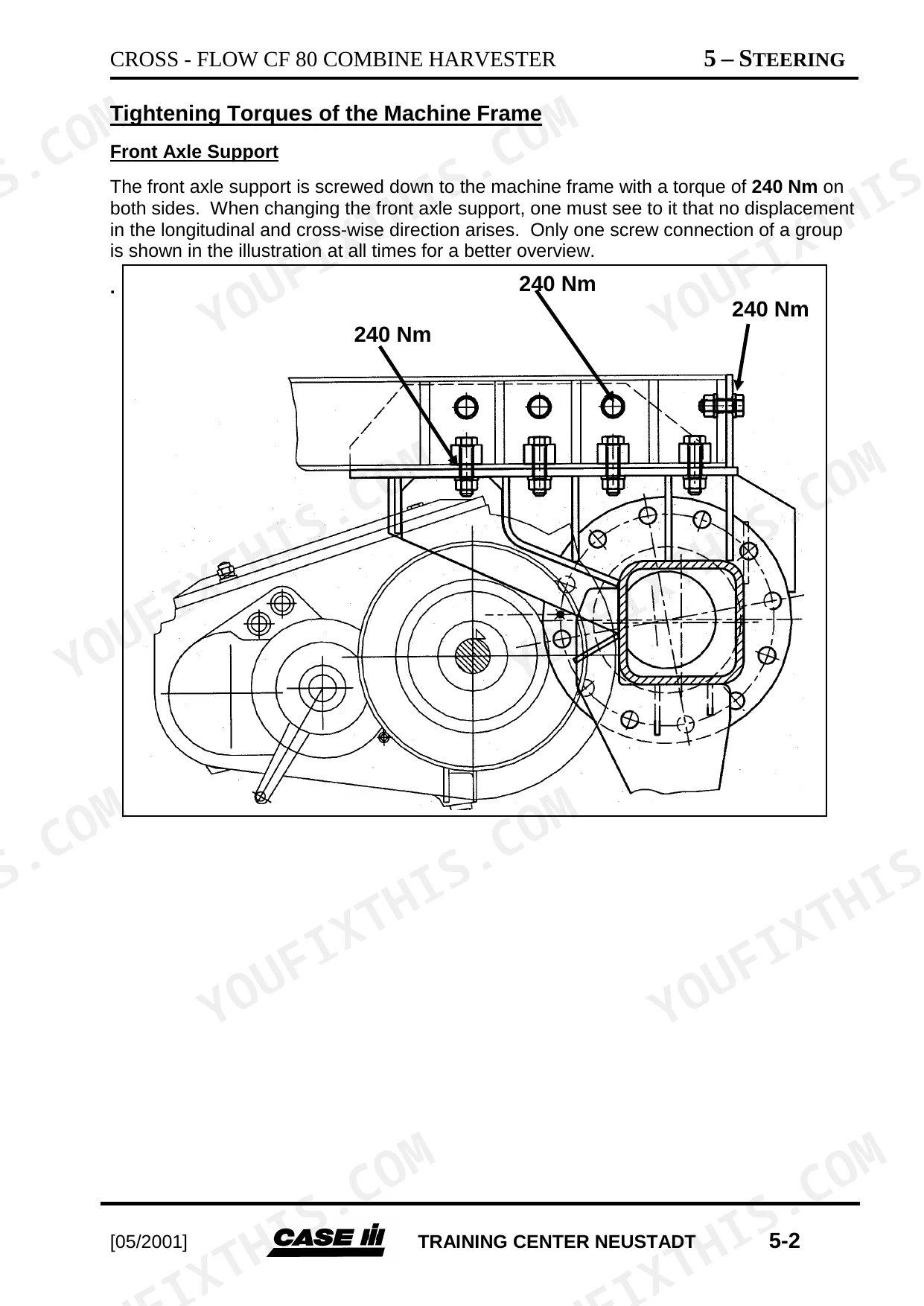
| Chassis, Steering & Brakes | - | Front Axle Support Tightening Torques, Rear Axle Support Tightening Torques, Straddle Gear, Gearbox, Transmission Care, Pump Adjustment, Troubleshooting Hydrostatic Ground Drive, Parking Brake, Brake Care, Bleeding the Two-Pedal Braking System, Adjustment of the Brakes of the Drive Axle, Service Intervals |
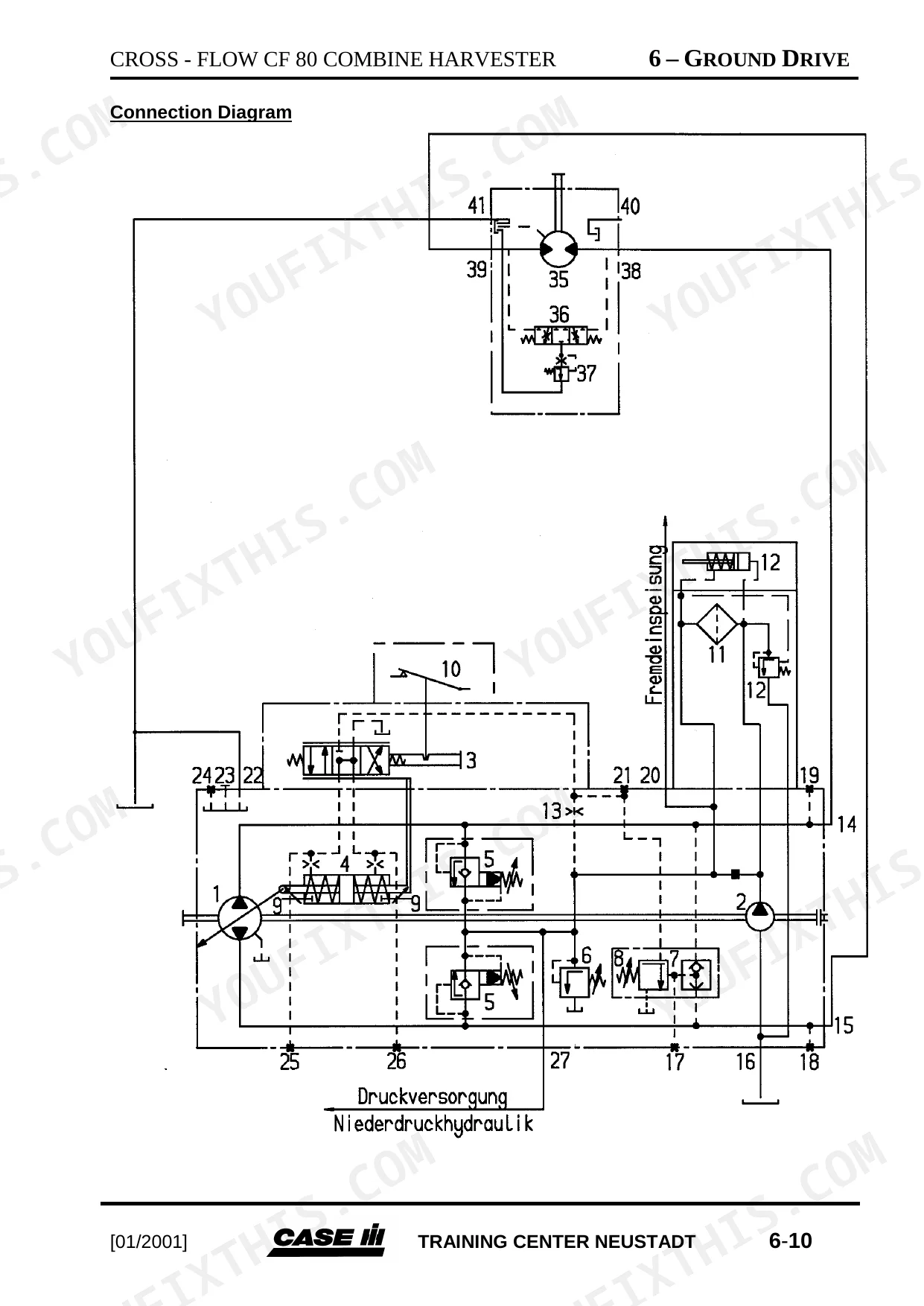
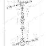
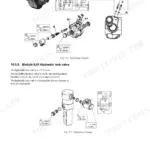
| Hydraulic System | - | Oils, Oil Filters and Oil Change, Oil Tank, Axial Reciprocating Pump A10VO45, Distributing Valve Design P, Header Hydraulics |
| Header & Feeder | - | Dividing Devices, Grain Lifter, Sickle Drive, Reel, Halm Auger, Shaft, Header Return, Field Tracking Design P |
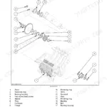
| Threshing & Cleaning | - | Stone Trap, Threshing Basket, Threshing Drum, Threshing Drum Variator, 2nd Drum, 3rd Drum, 4th Drum, Distributing Auger, Cleaning Unit Drive, Grain Pan, Sieves, Hillside Spreader Auger |
| Grain Handling, Discharge & Accessories | - | Elevators, Belt Drives, Belt Couplings, Grain Tank Top Unit, Grain Sampler, Auger Cover, Safety Clutch, Straw Chopper, Threshing Drum Reduction Gear, Guide Rails, Clover Huller, Rape Knife |
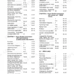
Quick Reference Specifications
| Specification | Value | Page |
|---|---|---|
| Engine fuel filter replacement interval | every 240 hours of operation (or once per year) | p. 64 |
| Engine oil and filter change interval | Every 240 operating hours, or once a year | p. 35 |
| Air filter cartridge replacement interval | once per year or after third clean-up | p. 68 |
| Water separation filter drain interval | 50 hours of operation | p. 76 |
| Reflux filter bypass valve opening pressure | 3.5 bar absolute | p. 409 |
| Threshing drum beater bars fixing bolts stud torque | 110 Nm | p. 501 |
| Threshing drum shaft clamp sleeve stud torque (right bearing) | 150 +30 Nm | p. 502 |
| Engine Oil Capacity with filter change | 21 liters | p. 35 |
| Coolant Filling Amount | 65 liters | p. 35 |
| CF80 Fuel Tank Capacity | 520/650 liters | p. 35 |
| Gearbox Oil Capacity | 7.0 liters | p. 36 |
| Spur Gear Oil Capacity | 4.5 liters | p. 36 |
Case IH CROSS-FLOW CF 80 Common Problems This Manual Covers
Case IH CF 80 hydraulic header won't lift, system pressure drops during operation
Check hydraulic oil level first; the tank holds approximately 60 liters (page 37). Inspect the reflux filter: the bypass valve opens at 3.5 bar absolute (page 409), so a pressure spike at that point means a clogged element. Examine the Axial Reciprocating Pump A10VO45 for wear, then work through the full troubleshooting sequence starting.
Manual Section: HydraulicsEngine overheating at full load, coolant temperature gauge climbing into red zone
Clean the rotary screen and cooler elements of all crop debris first; restricted airflow is the most common cause before any other diagnosis. Verify coolant level against the 65-liter system capacity (page 35). Inspect all hoses and seals for leaks. If temperature stays elevated after cleaning, pressure-test the cooling circuit for internal blockages before replacing the thermostat or water pump.
Manual Section: Engine p. 35Excessive grain loss through straw walkers, unclean sample in hopper during wet harvest
Adjust threshing drum speed within the 386-1,250 r.p.m. range (page 56) to match the crop. Work through the loss determination procedure to separate straw walker losses from cleaning losses before touching sieve or fan settings. Inspect grain pan rubber-metal connections for play; worn bushings let the pan drift and push grain into the tailings auger.
Manual Section: Cleaning Unit p. 56Engine won't start after sitting over winter, or rough idle with black smoke at throttle
Drain the water separator every 50 hours (page 76); water in the bowl is the most common hard-start cause after the machine has sat. Replace the fuel filter on the 240-hour schedule (page 64). Bleed the fuel system after any filter change. If rough running persists, inspect injector return lines for air entry points.
Manual Section: Fuel System p. 76Threshing drum vibrating or running rough, unusual noise from drum bearings during harvest
Remove the drum access panels and inspect beater bars for missing or cracked segments. Retorque fixing bolts to 110 Nm (page 501), then check shaft clamp sleeve studs at both bearing housings, torquing to 150 +30 Nm at the right (page 502) and left (page 503). Run the drum unloaded after reassembly and listen for any knock before cutting.
Manual Section: Threshing Unit p. 501Frequently Asked Questions
Torque specs for header drive bolts on CF 80 Cross Flow?
The tightening torque for the two hexagon head screws on the lower output shaft, which is part of the header drive, is 54 Nm. This is for clamping the drive disk to the profile with a flange on the shaft. p. 476
What are the replacement specifications for Engine fuel filter?
The engine fuel filter should be changed every 500 operating hours, or sooner if there is a noticeable drop in performance. The primary engine filter should also be replaced after every 500 hours of operation or if output drops. p. 76
What are the replacement specifications for Engine oil filter?
The engine oil and filter should be changed every 240 operating hours or once a year, whichever comes first. The oil capacity with a filter change is 21 liters. p. 35
Torque specifications for rotor bearings on CF 80 Cross Flow combine?
For the threshing drum shaft, the clamp sleeve for both the right and left bearings should be tightened with a stud torque of 150 +30 Nm. For the 3rd drum (separating drum), the stud torque is also 150 +30 Nm, and the two clamping screws at the drum body should be tightened with a torque of 70 Nm. p. 502
How will I receive this CROSS-FLOW CF 80 Service Manual?
This is a 552-page searchable PDF ready for immediate download. Works on any device, so pull it up on your phone while you're under the hood. No shipping, no waiting.
Can I print this CROSS-FLOW CF 80 manual?
Absolutely. No DRM or copy protection. Print the whole manual or just the pages you need. Any home or office printer works.
Does this CROSS-FLOW CF 80 manual include hydraulic schematics?
Yes, complete hydraulic schematics with flow diagrams, valve configurations, and pressure specifications are included.


Reviews
There are no reviews yet.