


All 332 pages of this Isuzu 4HK1-6HK1 Repair Manual (OEM #Lep 9-44060) focus on one machine: the 4HK1 and 6HK1 diesel engines as installed in CNH, Hitachi, JCB, and Sumitomo equipment. Inside you get the full engine mechanical teardown from cylinder head cover through crankshaft, a complete common rail fuel system section with injector and supply pump procedures, cooling and turbocharger service, EGR system troubleshooting, and wiring diagrams for the charging, starting, and preheating circuits. Torque tables run deep throughout: snug the fuel injector clamp bolt to 30 N·m, the injection pipe to 44 N·m, and the fuel supply pump gear nut to 64 N·m before you button anything up. Your machine is down. Get the factory number on the first try, not a forum estimate. Bookmarked and searchable — pull up any spec on your tablet right at the engine and get back to work.
What's Inside This Isuzu 4HK1-6HK1 Repair Manual
| System | Pages | Key Topics |
|---|---|---|
| Introduction | 4 | Units of Measure, International System, Mksa System, Conversion Table |
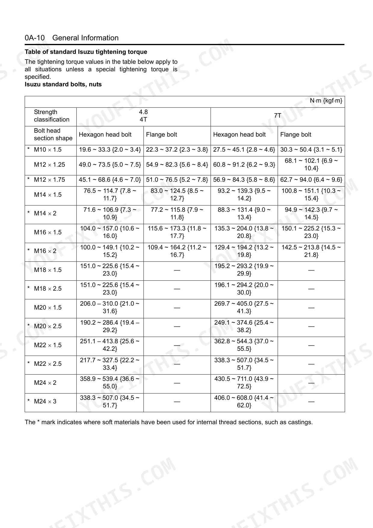
| General Information | 5-17 | Service Precautions, Liquid Gasket, Plastiguage, Standard Isuzu Tightening Torque, Designations for Isuzu Standard Bolt Heads, Terminology Definitions |
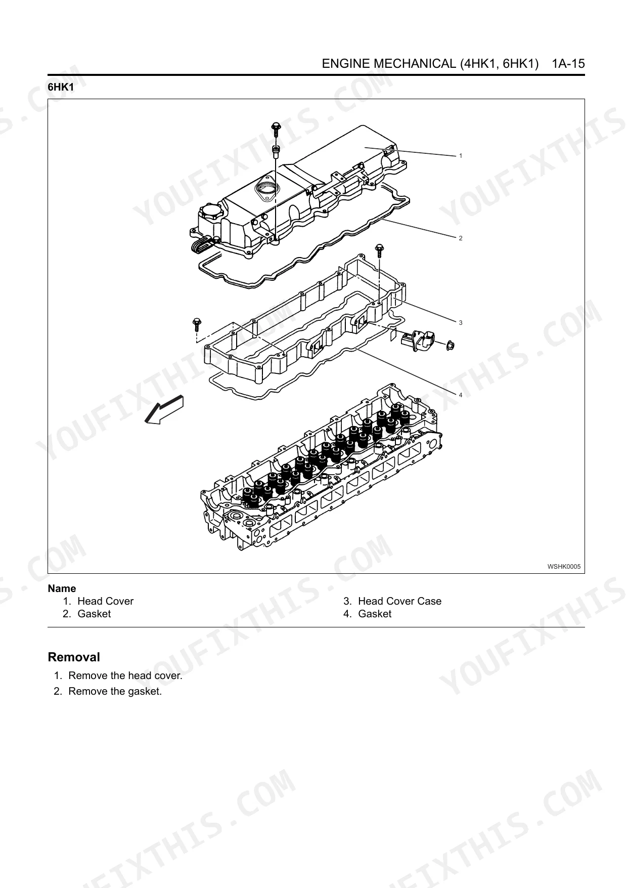
| Engine Mechanical | 18-196 | Cylinder Head Cover, Timing Gear Train, Rocker Arm Shaft Asm, Camshaft Asm, Piston, Connecting Rod, Crankshaft |
| Cooling System | 197-221 | Precautions on Service Work, Function Check, Main Data and Specifications, Water Pump, Thermostat, Drive Belt |
| Fuel System | 222-257 | Precautions on Service Work, Fuel Filter Asm, Fuel Injector, Fuel Supply Pump, Common Rail, Fuel System Diagram |
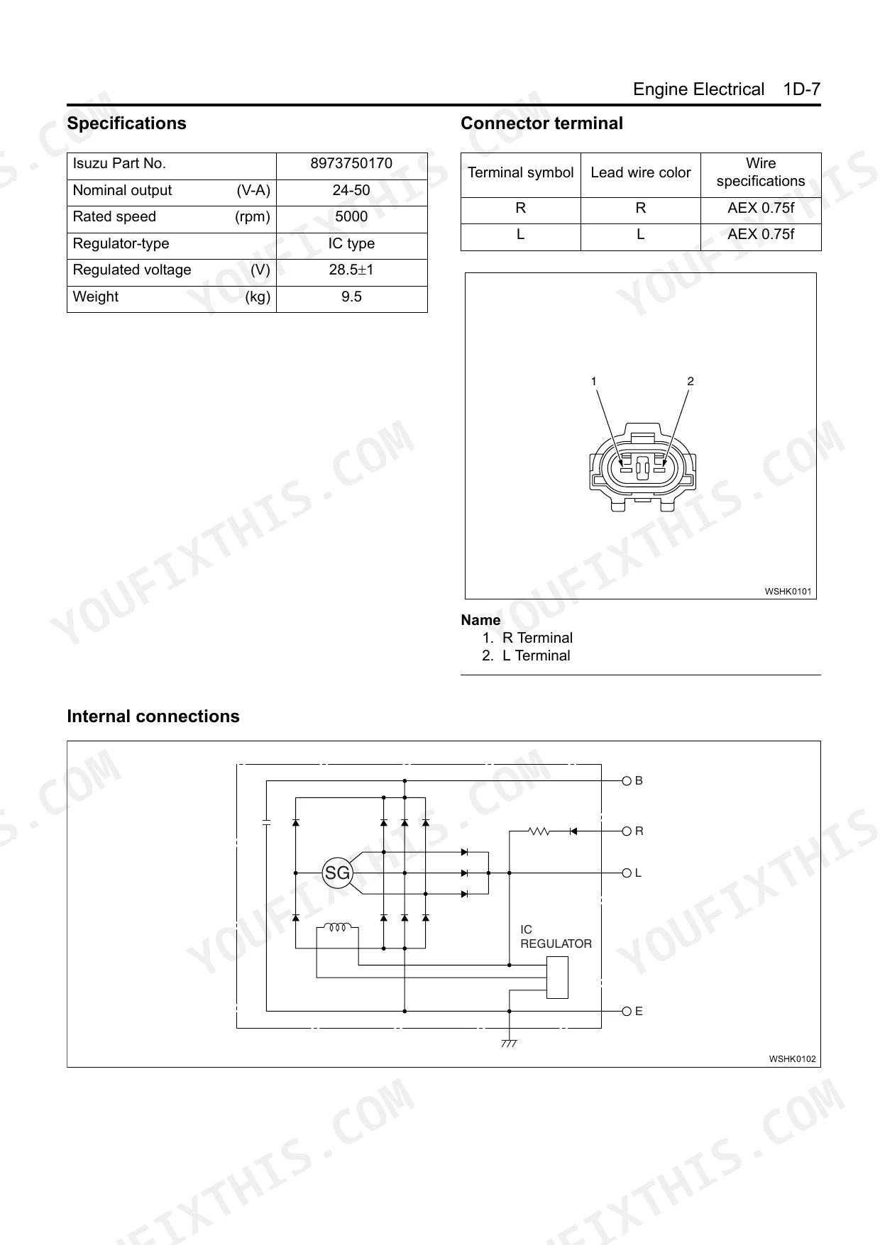
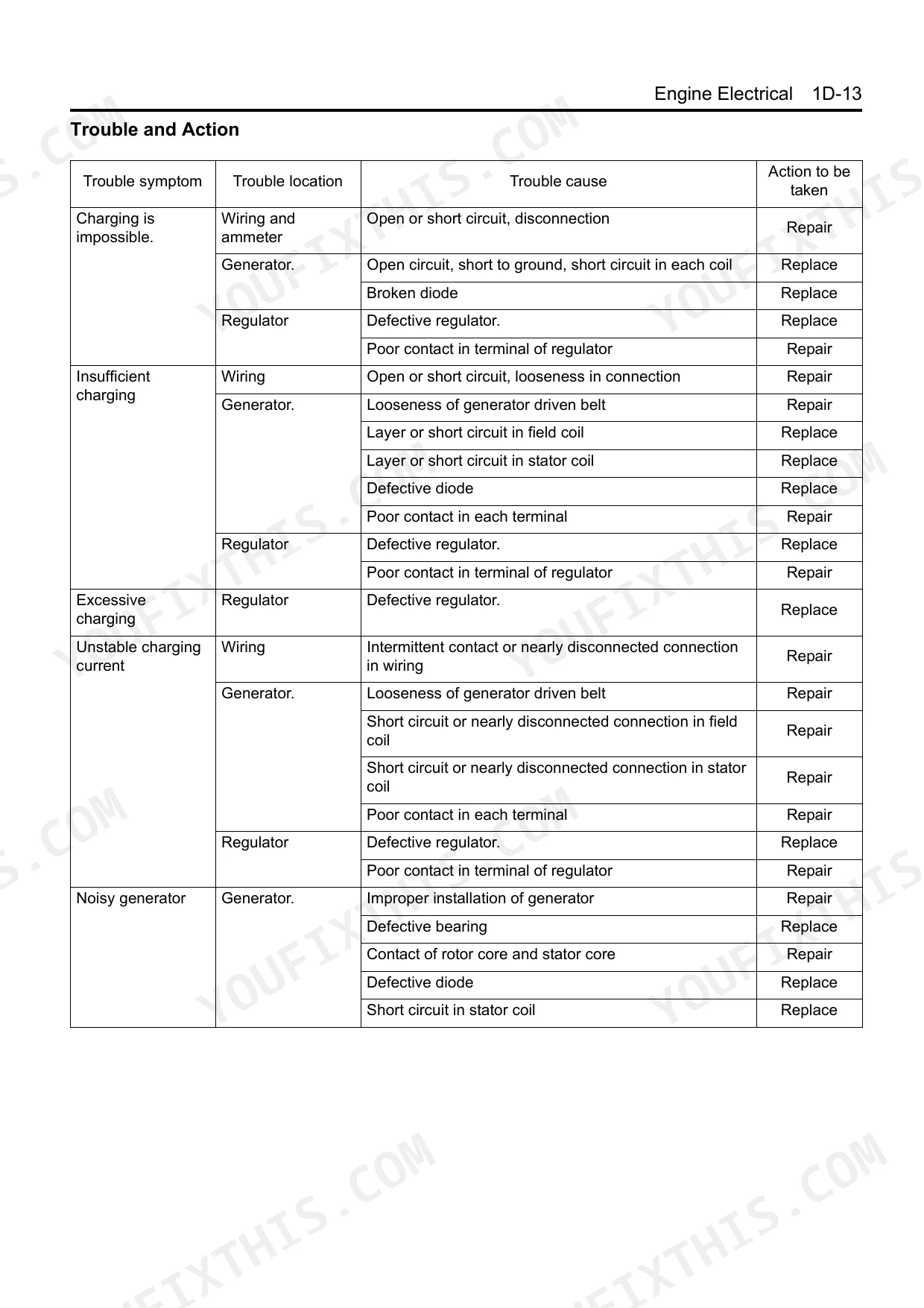
| Engine Electrical | 258-310 | Service Precautions, Charging System, Generator, Starting System, Starter, Preheating System |
| Exhaust System and Turbocharger | 311-332 | EGR System, EGR Valve and EGR Cooler, Exhaust System, Troubleshooting, Turbocharger, Measurement Tool |
Quick Reference Specifications
| Specification | Value | Page |
|---|---|---|
| Fuel Injector Clamp Bolt tightening torque | 30 N⋅m (3.0 kg⋅m/22 lb ft) | p. 241 |
| Fuel Injection Pipe tightening torque | 44 N⋅m (4.5 kg⋅m/32 lb ft) | p. 241 |
| EGR valve bolts tightening torque | 24 N⋅m (2.4 kg⋅m/17 lb ft) | p. 314 |
| EGR pipe bolts tightening torque | 28 N⋅m (2.9 kg⋅m/21 lb ft) | p. 314 |
| Fuel supply pump gear nut tightening torque | 64 N⋅m (6.5 kg⋅m/47 lb ft) | p. 245 |
| Fuel supply pump bracket bolts tightening torque | 19 N⋅m (1.9 kg⋅m/14 lb ft) | p. 245 |
| Crankshaft position sensor tightening torque | 8 N⋅m (0.8 kg⋅m/71 lb in) | p. 135 |
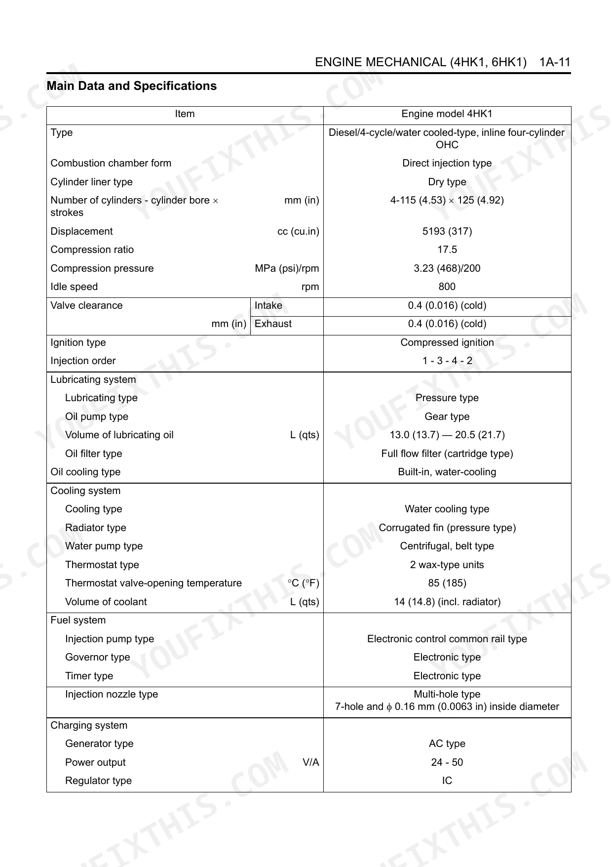
| Valve clearance (cold) | Intake 0.4 mm, Exhaust 0.4 mm | p. 23 |
| 4HK1 Volume of lubricating oil | 13.0 – 20.5 L | p. 28 |
| 6HK1 Volume of lubricating oil | 28 – 38 L | p. 29 |
| 4HK1 Volume of coolant | 14 L | p. 200 |
| 6HK1 Volume of coolant | 14.5 L | p. 160 |
Isuzu 4HK1-6HK1 Common Problems This Manual Covers
Isuzu 4HK1-6HK1 fuel injectors coked or common rail pressure low, rough idle and black smoke
Check common rail pressure at idle and compare against spec. Remove injectors and inspect for carbon deposits on nozzle tips. Reinstall with clamp bolt torqued to 30 N⋅m and injection pipe at 44 N⋅m (page 241). Replace any injector showing irregular spray pattern or visible carbon buildup on the pintle.
Manual Section: Fuel System p. 241Fault code P2005 stored, engine loses power noticeably under load
Inspect the EGR valve and cooler for carbon buildup before replacing any sensors. Clean the valve bore thoroughly and retest. If the valve is mechanically seized, reinstall with bolts torqued to 24 N⋅m and EGR pipe bolts at 28 N⋅m (page 314). Clear the fault code and run the engine under load to confirm the repair.
Manual Section: Exhaust System and Turbocharger p. 314HP3 or HP4 fuel supply pump noisy, engine loses rail pressure at high RPM
Replace the fuel filter first; a clogged element starves the HP pump and mimics pump failure. Verify pump drive timing before condemning the unit. Reinstall with gear nut at 64 N⋅m (page 245) and mounting bolts at 76 N⋅m (page 246). Confirm bracket bolts are at 19 N⋅m and recheck rail pressure at full throttle.
Manual Section: Fuel System p. 245Engine cranks but won't fire in cold weather, glow indicator lamp not cycling properly
Test each glow plug resistance with a multimeter before replacing the controller. Remove and reinstall plugs at 20 N⋅m (page 283). A failed plug reads open circuit or near-zero ohms. Follow the preheating system troubleshooting chart on to isolate indicator lamp faults from timer relay issues, then replace any plug that fails the resistance check.
Manual Section: Engine Electrical p. 283Turbocharger rattles on shutdown or shaft wobble detected, blue smoke at startup
Measure turbine shaft axial play before any disassembly. Service limit is 0.11 mm (page 317); a bearing housing exceeding that needs cartridge replacement, not adjustment. Inspect the oil drain line for blockage, since restricted drain causes seal failure and oil ingestion. Check exhaust system troubleshooting on page 316 for leaks that produce noise mimicking a failing turbo.
Manual Section: Exhaust System and Turbocharger p. 317Frequently Asked Questions
What is the torque spec for Isuzu 4HK1 main bearing bolts (M14) in Nm and lb.ft?
For Isuzu 4HK1 M14 main bearing bolts, the tightening torque involves a three-step process: first, tighten to 98 N⋅m (10.0 kg⋅m/72 lb ft); second, rotate an additional 30°; and third, rotate another 60°. This procedure is for bolts (1 – 10). p. 160
How to reset Isuzu 6HK1 fuel injection error P0200 post-replacement
After fuel injector replacement, perform the Fuel Injector Flow Rate Programming Procedure using a scan tool (TIS 2000) and the Service Programming System (SPS). Ensure all programming contents are entered correctly and successfully programmed, then turn off the ignition for 30 seconds. Finally, use the scan tool to check each programmed fuel injector flow rate and inspect for proper engine running condition and no DTCs. p. 239
What are the replacement specifications for Fuel injector?
When replacing fuel injectors, install each injector in its original cylinder position. Use new gaskets and O-rings for the injector clamps. Apply molybdenum to the clamp bolt threads and seating surfaces, then tighten the clamp bolts to 30 N⋅m (3.1 kg⋅m/22 lb ft) and the injection pipes to 44 N⋅m (4.5 kg⋅m/32 lb ft). Additionally, record all numbers from the QR plate on the replaced injector housing. p. 237
What are the replacement specifications for EGR valve?
For EGR valve replacement, insert a new gasket and temporarily fit the EGR valve. Then, temporarily tighten the bolts. The tightening torque for bolts 1 and 2 is 28 N⋅m (2.9 kg⋅m/21 lb ft), and for bolts 3, 4, 5, and 6, it is 24 N⋅m (2.4 kg⋅m/18 lb ft). p. 314
How quickly can I access this manual after buying?
Immediate download of the complete 332-page searchable Repair Manual. Access it on any device, from a laptop at your desk to a phone in the field.
Am I able to print pages from this manual?
Yes, print as many copies as you want, and there are no restrictions. Many mechanics print the section they need and bring it to the shop floor.
Are hydraulic system diagrams in this Isuzu 4HK1-6HK1 Repair Manual?
No, hydraulic schematics are not included in this manual.

Reviews
There are no reviews yet.