


Need to tear down the hydrostatic drive on your 2002-2007 compact backhoe loader? This 476-page JCB 1CX Service Manual PDF (OEM #9803/9960-4) covers the complete machine, including the Series 1, Series 2, 1CXWS, and 1CXT variants. You get full color-coded hydraulic schematics, complete electrical circuit diagrams, and step-by-step diagnostic procedures for tracking down drive motor faults. Open it up to find page after page of torque tables for zinc-plated and Dacromet fasteners, plus dedicated sections for rebuilding the hydrostatic pump and engine. Install a 0-35 bar pressure gauge in charge pressure gauge port A and verify the system hits a minimum of 7 bar while jogging the starter. Stop wasting hours guessing at test port locations. Grab this bookmarked download, load it on your shop tablet, and get your loader back in the dirt.
What's Inside This JCB 1CX Manual
| System | Pages | Key Topics |
|---|---|---|
| Introduction | 6-11 | - |
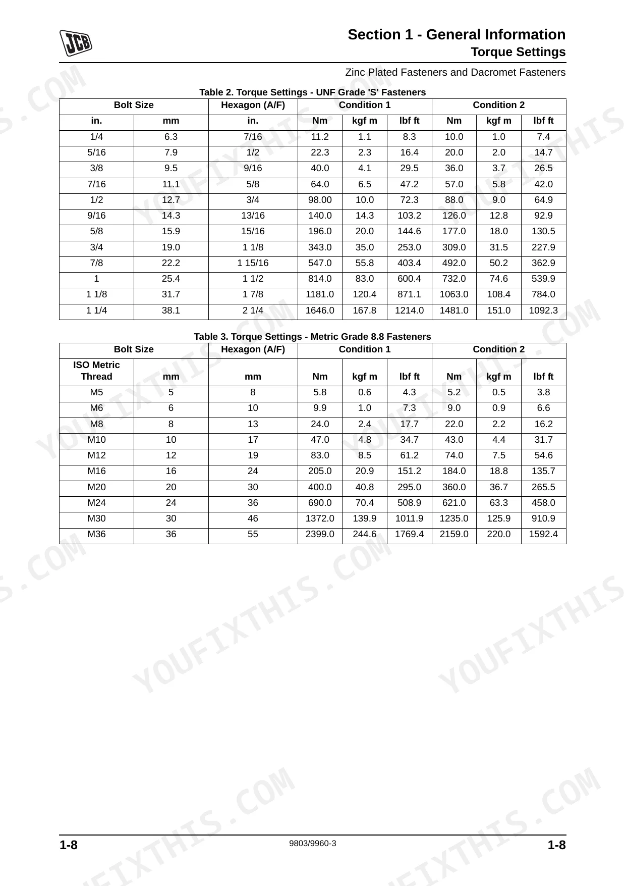
| Torque Settings | 12-19 | Zinc Plated Fasteners and Dacromet Fasteners (Introduction, Bolts and Screws, Hydraulic Connections, 'o' Ring Face Seal System, 'Torque Stop' Hose System) |
| Service Tools | 20-33 | Numerical List Section B - Body and Framework, Tool Detail Reference Section B - Body and Framework, Numerical List Section C - Electrics |
| Service Consumables | 34-35 | Sealing and Retaining Compounds |
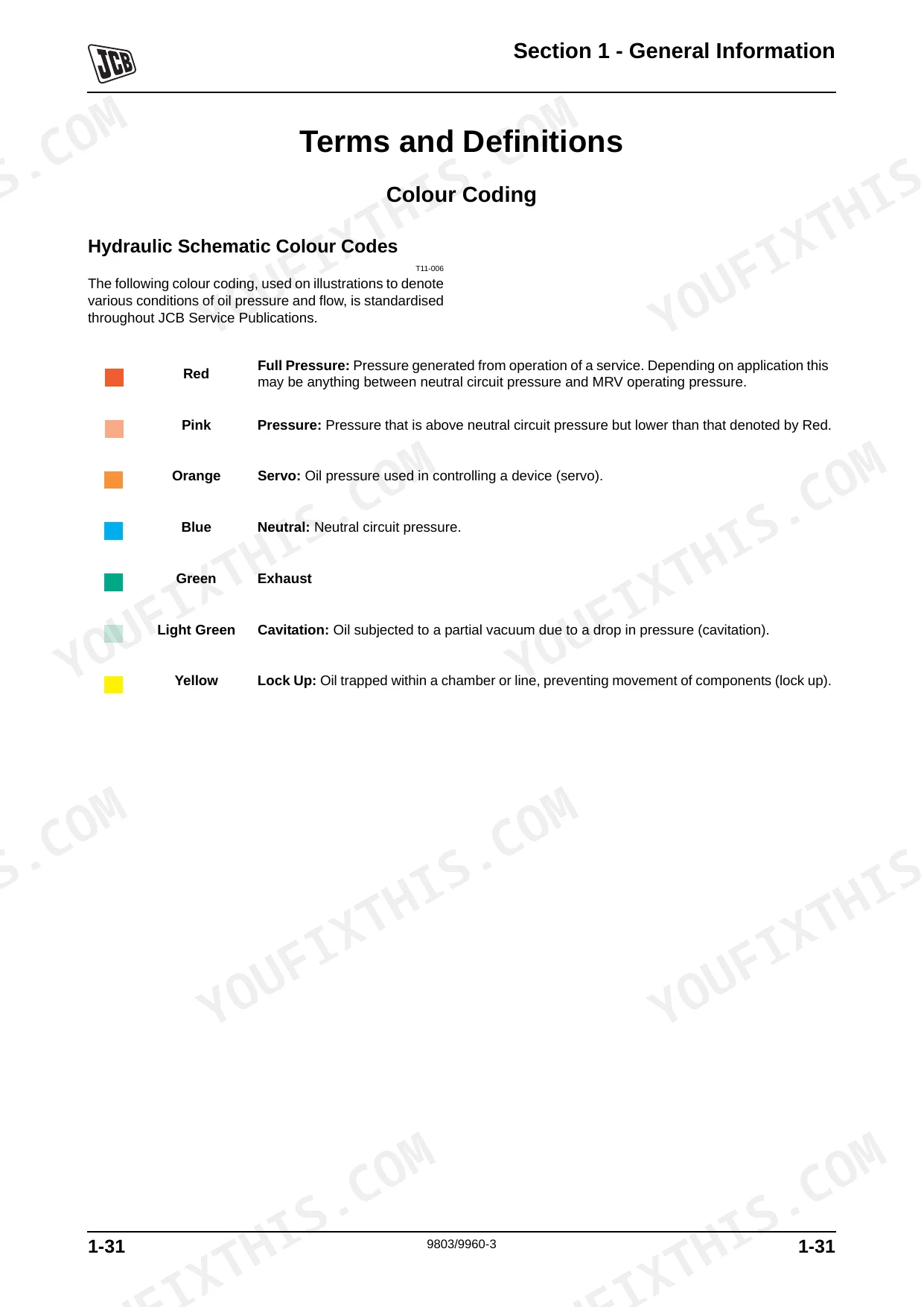
| Terms and Definitions | 36-37 | Colour Coding, Hydraulic Schematic Colour Codes |
| Care and Safety | 38-53 | Safety Notices, Safety Check List |
| Maintenance | 54-128 | Service Requirements, Health and Safety, Service Schedules, Fluids, Lubricants and Capacities, Prepare the Machine for Maintenance, Cleaning the Machine, Greasing |
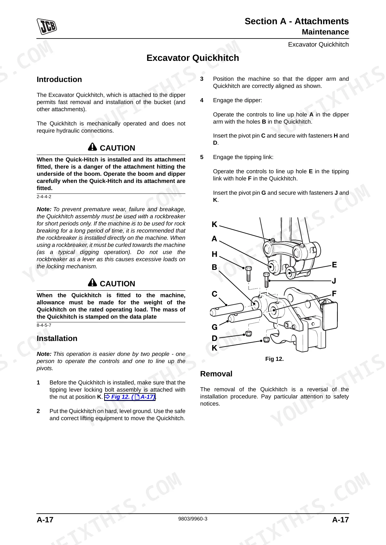
| Attachments | 129-156 | Service Procedures |
| Body and Framework | 157-190 | Service Procedures, Glazing, Excavator, Cab/Canopy Door |
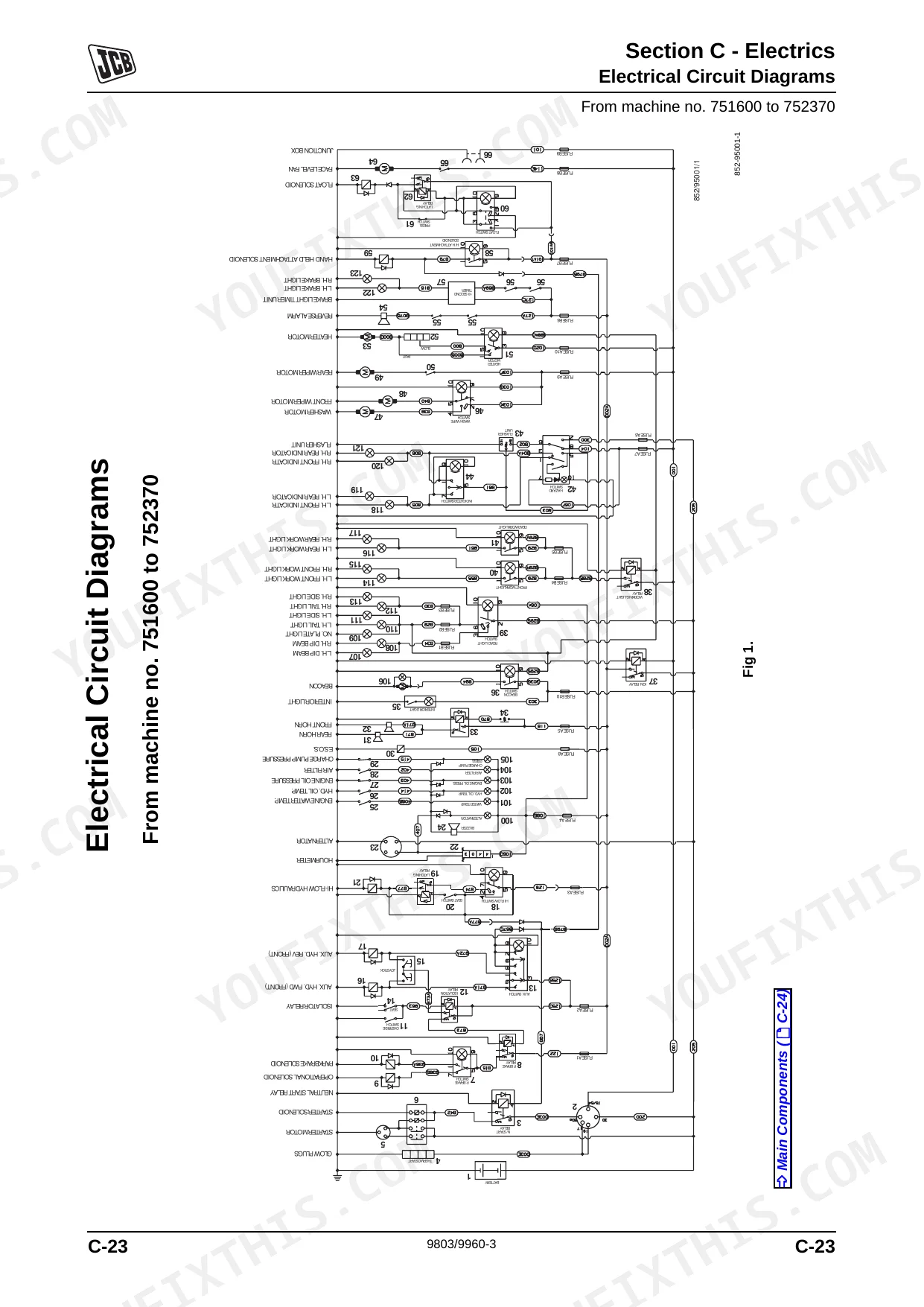
| Electrics | 191-248 | Technical Data, General, Battery, Alternator, Electrical Circuit Diagrams, Harness Data, Control Systems |
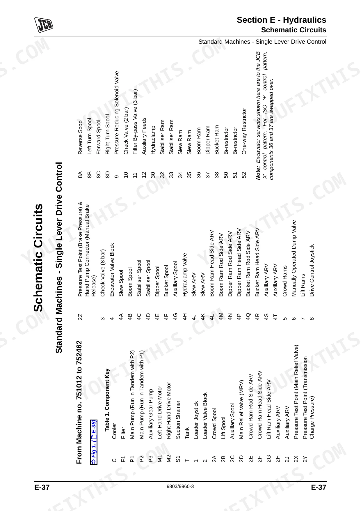
| Hydraulics | 249-418 | Technical Data, General, Operation, Schematic Circuits, Fault Finding, Pressure Testing, Pumps, Valves (Series 1 Machines) |
| Transmission | 419-428 | Wheels and Tyres |
| Brakes | 429-434 | Towing and Winching |
| Tracks | 435-466 | Basic System and Operation, Track Damage |
| Engine | 467-476 | Technical Data |
Quick Reference Specifications
| Specification | Value | Page |
|---|---|---|
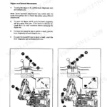
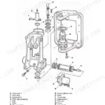
| Start-up Procedure for Pumps | Place the machine safely onto blocks, so that all four wheels are clear of the ground. Ensure that the machine is stable. Check that the pump inlet line from the hydraulic filter to the pump unit is filled with fluid, by 'cracking' the hose connection at the rear main pump. Install a 0 - 35 bar (0 - 500 lb/in2, 0 - 35 kgf/cm2) pressure gauge in the charge pressure gauge port A, to monitor the charge pressure. After machine serial no. 751012 a test point is provided which, up to serial no. 751715, is positioned under the pump as shown at B. Remove the ESOS fuse to prevent the engine from starting. With the Drive Control Lever (in the cab) at Neutral, 'jog' the engine using the starter. The pressure gauge should show a small rise in pressure as the engine turns. If so, replace the ESOS fuse and operate the starter whilst slowly increasing the throttle lever setting until the engine starts and runs at the lowest possible speed. As air leaves the system, the charge pressure (as indicated on the gauge) should rise to a minimum of 7 bar (7 kgf/cm2 100 lb/in2). If the charge pressure is incorrect, shut-down and determine the cause. Once the correct charge pressure has been established, operate the drive system 10 times in all directions with the engine at idle then slowly increase the engine speed whilst continuing to operate the system. Finally operate the system in all directions several times with the engine running at maximum speed. Shut down engine and remove the pressure gauge. Check the system fluid level and top up as necessary. | p. 334 |
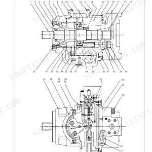
| Shaft Seal Replacement (Hydrostatic Pump) | Renew O-ring 5 and lip seal 6. Coat outside diameter of new lip seal 6 with suitable sealant. Press lip seal into shaft bearing side of seal carrier 3. Lubricate inside diameter of lip seal 6 with petroleum jelly. Install new O-ring 5 onto seal carrier 3 and lubricate with petroleum jelly. Wrap splined end of shaft 2 with thin plastic to prevent damage to the lip seal during installation. Slide seal carrier 3 over shaft 2 and press into position in the pump body recess. Hold inward pressure against shaft 2, refit circlip 1 to secure the assembly. | p. 336 |
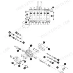
| Shaft Seal Replacement (Drive Motors) | The space between the lips of shaft seal 11 should be filled with JCB HP Grease. | p. 386 |
| General Gasket Replacement | Renew whenever disturbed unless otherwise instructed. | p. 50 |
| JCB Multi-Gasket | Part No. 4102/1212, Quantity 50 ml | p. 34 |
| Auxiliary Pump - Standard Displacement | 48 l/min (10.5 UK gal/min, 12.7 US gal/min) at 3000 rev/min | p. 255 |
| Auxiliary Pump - Standard Maximum Working Pressure | 185 - 192 bar (2683 - 2785 lbf/in2, 188 - 196 kgf/cm2) | p. 255 |
| Main Relief Valve (M.R.V.) at 1500 rev/min | 207 bar (211 kgf/cm2, 3006 lbf/in2) | p. 256 |
| Pressure Reducing Solenoid Valve Regulated Pressure | 24 Bar (348 lbf/in2, 24.47 kgf/cm2) | p. 256 |
| Extending Dipper Wear Pads Replacement Torque (Item C nuts) | 50 Nm (37 lbf ft) | p. 67 |
| Adjusting the Bottom Wear Pads Clearance (Gap at G) | no greater than 1.5mm (1/16 inch) | p. 68 |
JCB 1CX Common Problems This Manual Covers
JCB 1CX front loader or backhoe hydraulics become weak, erratic, or fail to move under load p. 320
Test the main relief valve pressure to verify it reads 207 bar. Inspect the loader circuit fault finding guide on page 320 for low pump flow or incorrect charge pressure. Drain and replace the system fluid if the capacity drops below the required 80 Litres.
Manual Section: Loader Circuit Fault FindingExtending dipper arm chatters or feels excessively loose during heavy excavation operations p. 68
Measure the bottom wear pads clearance gap at point G. Verify the gap is no greater than 1.5mm as shown on page 68. Adjust the pads if necessary and torque the extending dipper retaining nuts to exactly 50 Nm according to page 67.
Manual Section: MaintenanceHydrostatic transmission responds poorly or drive motors lack pushing power when moving the machine p. 366
Check the transmission changeover valve operating conditions detailed on page 366. Verify the normal pressure reaches 20 Bar and confirm the maximum tank line pressure stays at or below 3 Bar. Test the charge pressure and inspect drive motor shaft seals for grease retention.
Manual Section: Hydrostatic Transmission Fault FindingTrack system slips or vibrates violently while driving over uneven rough terrain p. 461
Inspect the outer track rubber for fast abrasion. Replace the track when lug wear reaches the limit specified on page 461. Verify the core bars show below approximately 20 percent abrasion. Check the sprocket mounting bolts and torque them to 300 Nm.
Manual Section: Track Damage and Repair ProceduresFrequently Asked Questions
How do I reset the JCB 1CX hydraulic system?
The manual describes a "Start-up Procedure" for the hydrostatic pump after a new installation or pump/motor removal. This involves placing the machine on blocks, checking the pump inlet line, installing a 0-35 bar (0-500 lb/in2) pressure gauge, "jogging" the engine with the ESOS fuse removed, then running the engine at idle and operating the drive system 10 times in all directions, and finally at maximum speed.
What do JCB 1CX error codes mean?
The manual provides a table of "Aux Fault Blink Codes" for the auxiliary system. For example, a "1 Long Flash 1 Short Flash" indicates "Joystick thumb wheel not in centre position", and a "1 Long Flash 3 Short Flashes" indicates "Aux 5V supply High value" with a test method of "12V to pin B of voltage reg".
How do I troubleshoot JCB 1CX low hydraulic pressure?
To troubleshoot low hydraulic pressure, refer to the "Loader Circuit" fault finding table on page 320. If there is "Insufficient hydraulic fluid," check for leaks and top up as required. If "Low loader pump flow" is suspected, check pump flow and service or replace the pump if necessary.
How to reset JCB 1CX hydraulics after service
After servicing the hydraulic system, perform the "Start-up Procedure" for the hydrostatic pump. This involves installing a 0-35 bar (0-500 lb/in2) pressure gauge, "jogging" the engine with the ESOS fuse removed, then operating the drive system 10 times in all directions at idle and then at maximum speed to ensure proper function and air expulsion.
How will I receive this Service Manual?
A 476-page Service Manual in searchable PDF format, available the moment you complete checkout. View on computer, tablet, or phone, with no shipping wait.
Are there any print restrictions on this manual?
Absolutely. No DRM or copy protection. Print the whole manual or just the pages you need. Any home or office printer works.
Can I find wiring schematics in this JCB 1CX manual?
Yes, full electrical schematics are included with wire colors, connector locations, and circuit descriptions.
Reviews
There are no reviews yet.