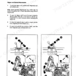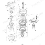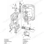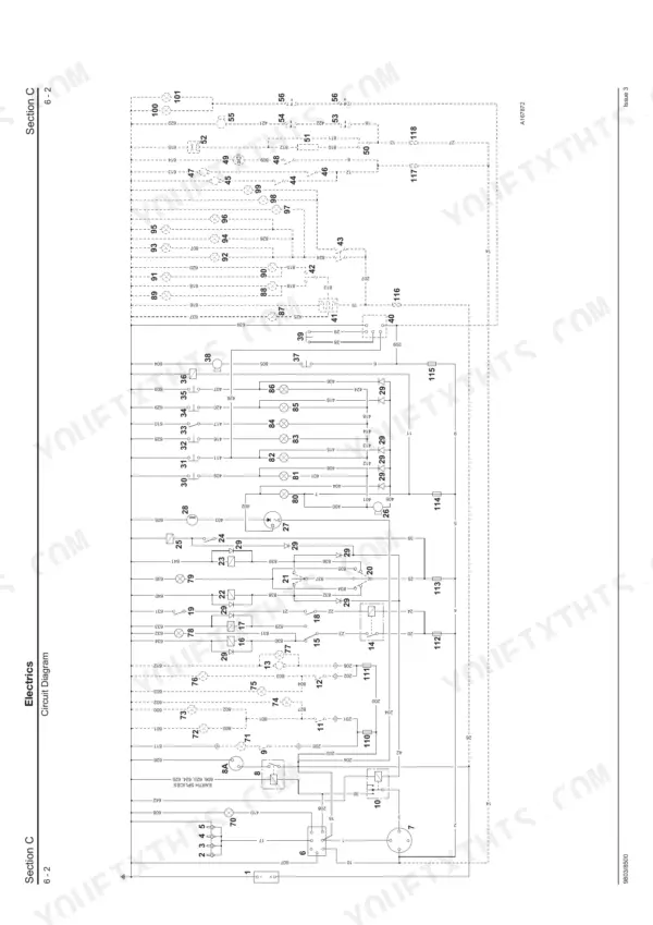
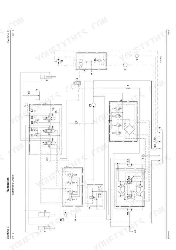
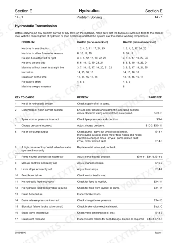
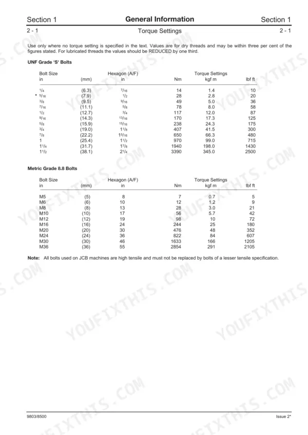
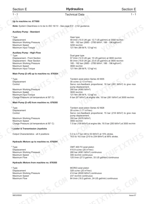


Working on a machine? This 254-page JCB Robot 150, Robot 165, 1CX, 185 and Skid Steer Loader service manual (OEM #9803/8500) breaks down every mechanical and electrical system for these models, plus the 1CX HF and 185 HF variants. Open up detailed wiring diagrams tracing every harness across the chassis, and study hydraulic schematics showing exactly how the servo joysticks and drive motors interact. Exploded views map the wheel hubs, loader arm struts, and engine components to guide your teardown. Lock down the eight-bolt roadwheel retaining bolts to 220 Nm and tighten the main hydraulic pump connections to 45-50 Nm before firing up the engine. Download this bookmarked file directly to your tablet, jump to the spec you need, and finish the repair.
What's Inside This Manual
| System | Pages | Key Topics |
|---|---|---|
| Care and Safety | 14-21 | Safety Notices, General Safety, Operating Safety, Maintenance Safety, Safety Decals |
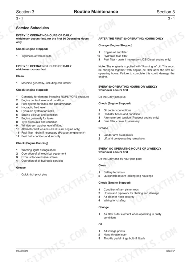
| Routine Maintenance | 22-56 | Fluids, Capacities and Lubricants, Fuel System, Service Schedules, Loader Arm Safety Strut, Greasing, Electrical System, Hydraulic System |
| Optional Attachments | 57-77 | Quick Release Couplings, Connecting Disconnecting Hydraulic Hoses, Shovels, Pallet Forks, Manure Silage Fork with Top Grab, Attachment Frame, Backhoe Attachment |
| Body and Framework | 78-87 | Seat and Floor Plate, Glazing, Door, Loader Arm |
| Electrics | 88-121 | Technical Data, Circuit Protection, Test Methods, Battery, Alternator, Starter Motor, Circuit Diagrams, Wire Harness Numbers |
| Controls | 122-127 | Safety Restraint Bar, Throttle Controls, Throttle Cable |
| Technical Data From Machine Number 677001 to 677999 | 131-136 | Technical Data Up to Machine Number 677000 |
| Loader Valve Neutral Circuit | 137-153 | Hydraulic Contamination, Technical Data From Machine Number 678000, General Description, Auxiliary Gear Pump, Machine Neutral Circuit |
| Pumps | 154-185 | Drive Motor Operation, Pressure Reducing Solenoid Valve, Transmission Operation |
| Problem Solving | 186-196 | |
| Valves | 197-210 | |
| Servo Joysticks | 211-218 | Pressure Reducing Solenoid Valve, Check Valve, Brake Valve |
| Rams | 219-222 | |
| Schematic Hydraulic Circuit | 223-238 | Hydraulic Tank, Hydraulic Filter |
| Transmission | 239-246 | Tyres and Wheels, Wheel Hub Assembly Up to Machine Number 676701, Wheel Hub Assembly From Machine Number 676702 |
| Brakes | 247-249 | Preparation for Towing Winching Up to Machine Number 676354, Preparation for Towing Winching From Machine Number 676355 |
| Engine | 250-254 | Specification, Removal and Replacement |
Quick Reference Specifications
| Specification | Value | Page |
|---|---|---|
| Roadwheel retaining bolts (8 bolt fixing) | 220 Nm (162 lbf ft, 22 kgf m) | p. 240 |
| Roadwheel retaining bolts (6 bolt fixing) | 405 Nm (298 lbf ft, 41 kgf m) | p. 240 |
| Hydraulic Connections (Pumps) | 45 - 50 Nm (4.6 - 5.1 kgf m, 33 - 37 lbf ft) | p. 160 |
| Hydraulic Connections (Drive Motors) | 44-50 Nm (33-37 lbf ft, 4.6-5.1 kgf m) | p. 180 |
| Hydraulic Filter Type | High Pressure Spin - On | p. 132 |
| Main Hydraulic Filter Clearance | 5 micron | p. 132 |
| Engine Oil and Filter Replacement Interval (first) | After the first 50 Operating Hours only | p. 27 |
| Engine Oil and Filter Replacement Interval (routine) | Every 250 Operating Hours or Monthly | p. 28 |
| Fuel Filter Drain Interval | After the first 50 Operating Hours only | p. 27 |
| Fuel Filter Drain Interval | Every 50 Operating Hours or Weekly | p. 27 |
| Seat Belt Replacement Criteria | Replace if damaged, worn, or after an accident. Fit a new seat belt every three years regardless of condition. | p. 35 |
| Seat Belt Mounting Bolts Torque | tightened (no specific value provided) | p. 35 |