


Mastering the daily upkeep of your heavy equipment starts here with this 110-page JCB Vibromax VM 132 D/PD, VM 146 D/PD, VM 166 D/PD, VM 200 D/PD, VM 132 – 200 D / PD, vibratory single drum roller operator manual PDF (OEM #07242/28435A). You get complete hydraulic circuit diagrams and full electrical system routing to keep your machine running smoothly. Open to the routine maintenance schedules for exact fluid capacities, grease points, and safe operating procedures for both smooth and tamping foot equipment. Lock down the wheel nuts to a precise 560 to 600 Nm, and verify the multiple-function valve bypass screw is tightened to exactly 40 Nm before towing. Don't let neglected maintenance kill your job site productivity. Grab this bookmarked download, open it on your tablet in the cab, and keep your roller packing dirt.
What's Inside This JCB Vibromax VM 132–200 D/PD Series Operator Manual
| System | Pages | Key Topics |
|---|---|---|
| Brief Description of the Machine | 6 | Front, Rear, Right-Hand Side, Left-Hand Side, Smooth Drum Shells, Tamping Foot Drum Shells |
| Product Identification and Serial Numbers | 7 | Model, Serial Number, Drum Drive Gear Box, Steering Unit, Rear Axle, Vibration Motor |
| Identifying the Machine Parts | 8-9 | Articulation Joint, Smooth Drum, Lifting and Towing Eyes, Operator’s Stand, Battery, Hydraulic Oil Tank |
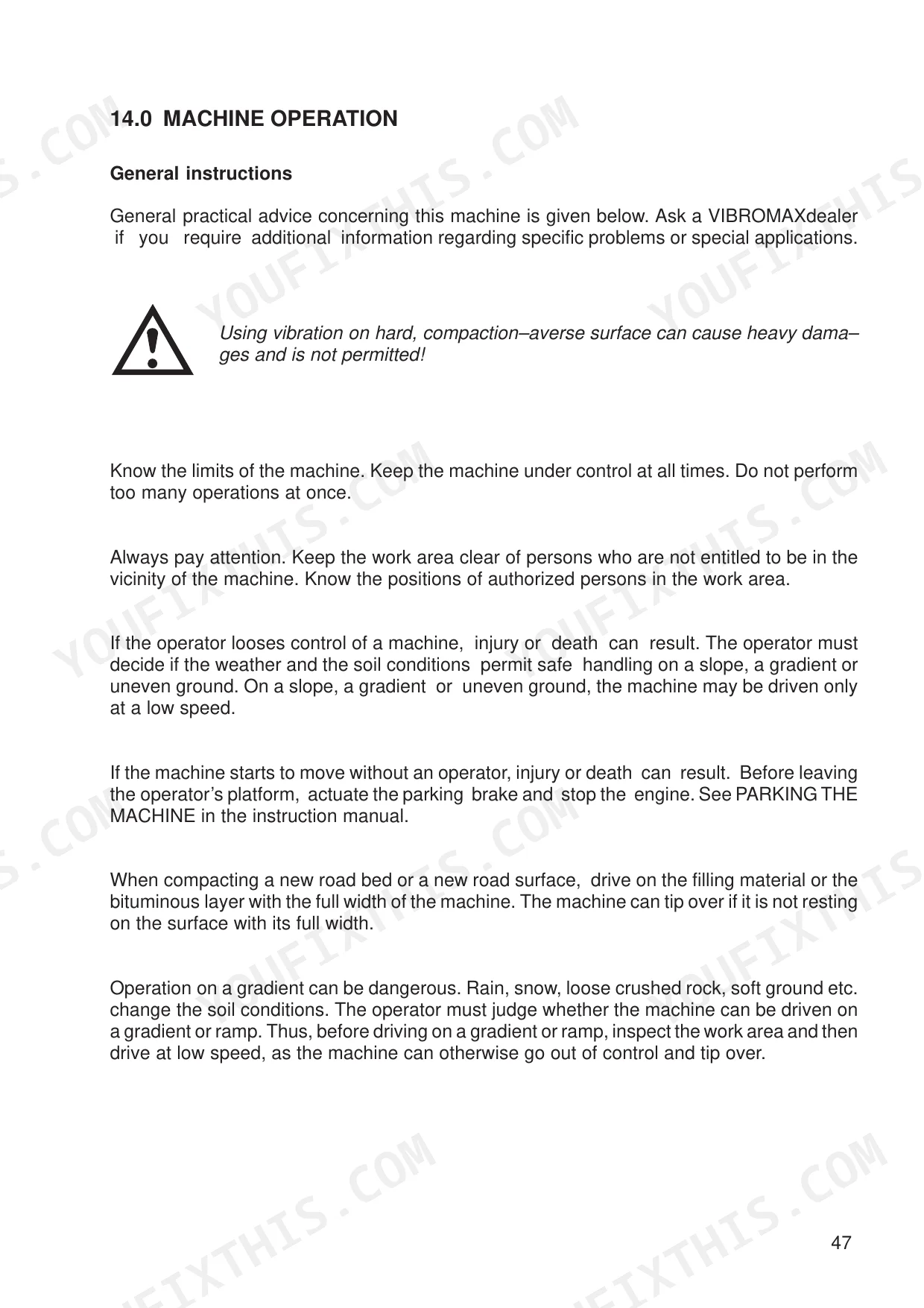
| Basic Safety Notes | 10-19 | Basics and Permissible Gradient, Organizational Measures and Staff Duties, Safety Notes for Operation, Special Dangers and Transport |
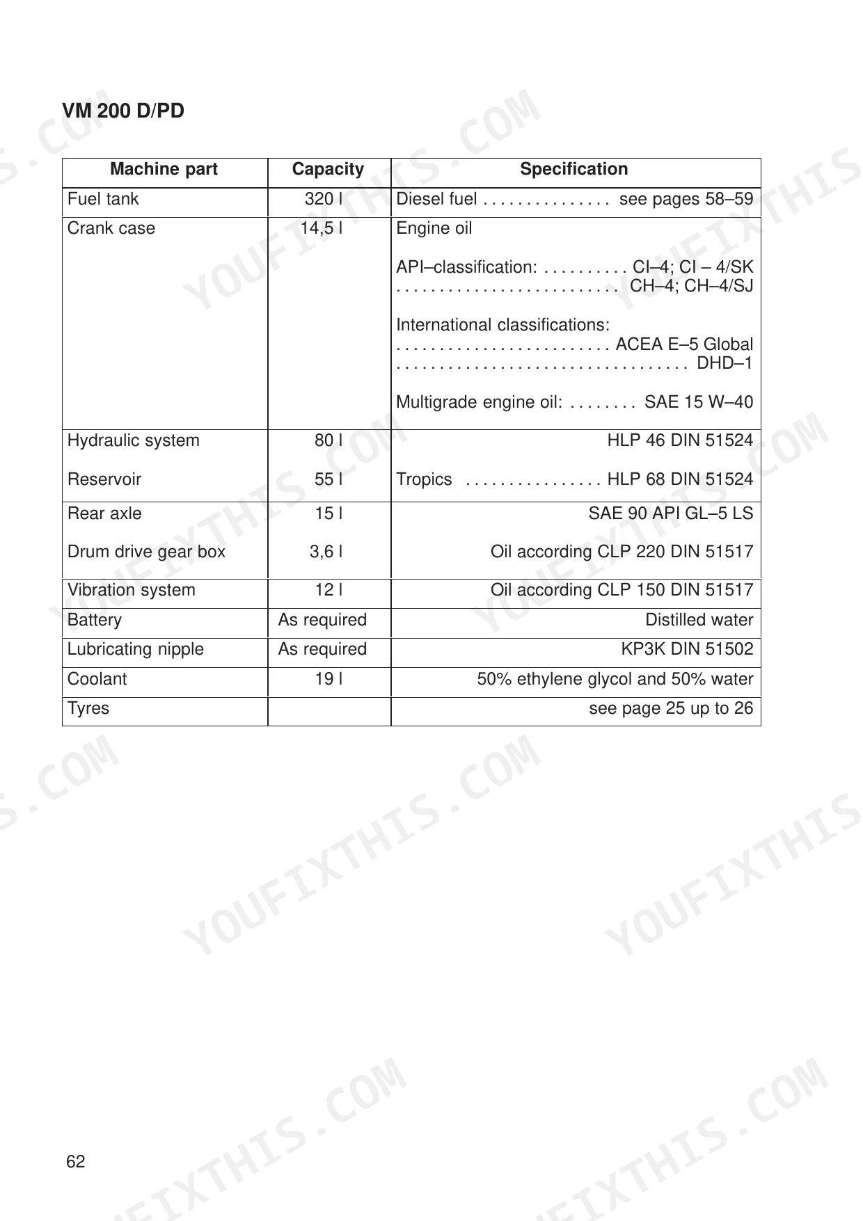
| Technical Data | 20-29 | Vm 132 D/PD Specifications, Vm 146 D/PD Specifications, Vm 166 D/PD Specifications, Vm 200 D/PD Specifications |
| Decals | 30-31 | Safety Decals, Note Decals, Lifting and Towing Eyes Decal, Instrument Panel Decal (Cab or ROPS), Instrument Panel Decal (No Cab) |
| Hand Signals | 32-33 | Start the Engine, Stop the Engine, Drive Forward, Drive Back, Drive Further by This Distance, Stop and Wait |
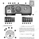
| Operator's Stand | 34-38 | Overview and Console |
| Operator's Stand and Cab | 39-40 | Cab |
| Special Equipment | 41-42 | Tamping Foot Equipment, Tamping Foot Shells, Levelling Equipment, Heating, Air Condition, Fan Nozzles |
| ASS-Switch | 43 | ASS-switch Location, Drum Type, Switch Position |
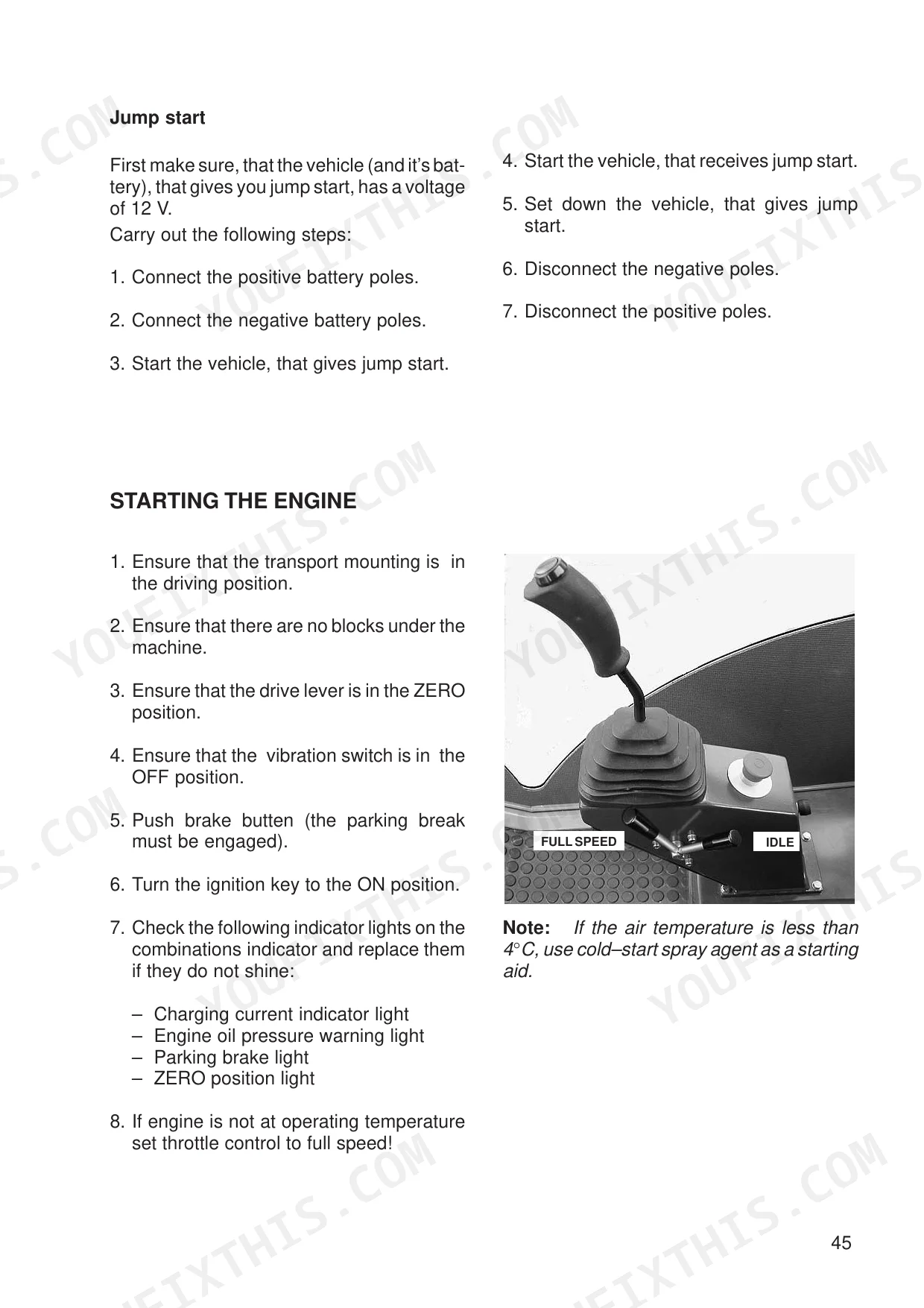
| Instructions for Safe Operation | 44-48 | General Information, Before Starting the Engine, Engine Starting Aids, Starting the Engine |
| Machine Operation | 49-51 | General Instructions, Machine Operation Without Vibration, Machine Operation with Vibration |
| Parking the Machine | 52 | Vibration Switch, Drive Lever, Engine Throttle Control, Parking Brake Switch, Ignition Key, Blocks |
| Towing the Machine | 53 | Tow-Bar, Transport Mounting, Bypass Screw, Multiple-Function Valve, Towing Valve, Brake System |
| Preparing the Machine for Transport | 54 | Transport Vehicle, Wheels, Blocks, Parking Brake Switch, Transport Mounting, Lifting and Towing Eyes, Tyres, Air Pressure |
| Before Maintenance/Lubrication | 55-59 | General Information, Transport Mounting, Access to Components |
| Notes for Safe Operation | 60-64 | Diesel Fuel, Fuel Storage, Minimum Requirements for No 2 Diesel Fuel, Fluids and Lubricants |
| Running-In Period – Maintenance Schedule | 65-83 | Maintenance Schedule, Grease and Fluid Levels, Engine Lubricating System, Air Filter, Engine Cooling System, Windscreen Washer System, Engine Fuel System |
| Storing the Machine | 84-87 | Initial Operation After Storage |
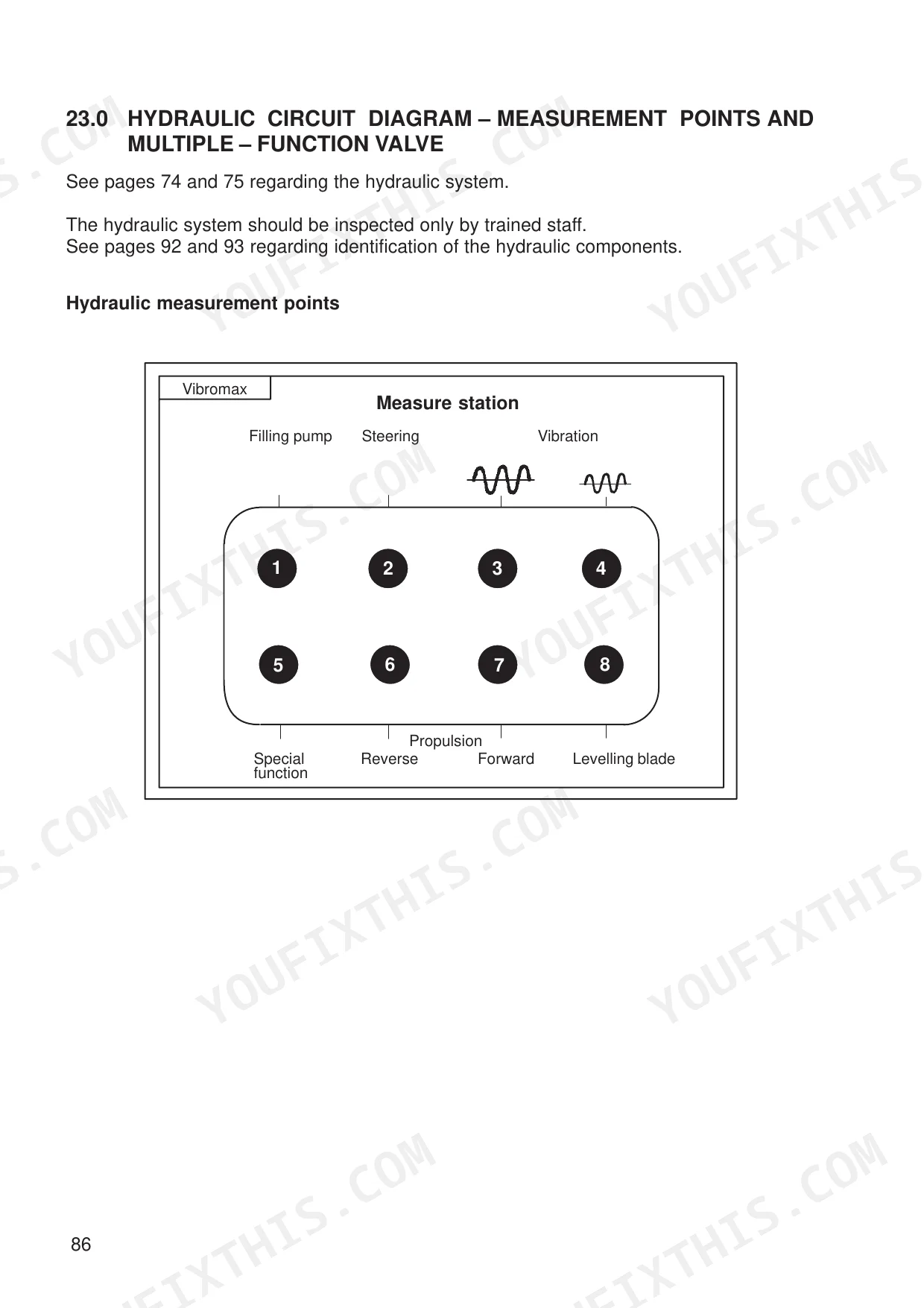
| Hydraulic Circuit Diagram – Measurement Points and Multiple Function Valve | 88-95 | Hydraulic Functional Description, Hydraulic Circuit Diagram, Identifying the Hydraulic Components |
| Electrical System | 96-110 | Battery, Fuses, Relays, Changing Bulbs, Electrical System Circuit Diagram |
Quick Reference Specifications
| Specification | Value | Page |
|---|---|---|
| All Models | ||
| Tightening torque for Vulcollan scraper screws on drum | 185 to 197 Nm | p. 80 |
| Tightening torque for scraper nuts on drum frame | 366 to 390 Nm | p. 80 |
| Tightening torque for wheel nuts | 560 to 600 Nm | p. 84 |
| Tightening torque for bypass screw (item 1) on multiple-function valve | 40 Nm | p. 92 |
| Tightening torque for multiple-function valve main body | 90 Nm | p. 92 |
| Hydraulic System Capacity | 80 l | p. 62 |
| Coolant Capacity | 19 l | p. 62 |
| Engine Operating Speed | 2200 rpm | p. 21 |
| VM 132 D/PD | ||
| Fuel Tank Capacity | 400 l | p. 62 |
| Crank Case Oil Capacity | 14.2 l | p. 62 |
| VM 132 D/PD Tyre Pressure | 0.9 to 1.4 bar | p. 21 |
| VM132D | ||
| VM 132 D/PD Operating Weight, max. | 13000 kg | p. 21 |
JCB Vibromax VM 132–200 D/PD Series Common Problems This Manual Covers
JCB Vibromax VM 132 D/PD vibrating excessively during transit and wheel lug nuts loosening after rough terrain use p. 84
Inspect the wheels and verify tyre pressure is between 0.9 to 1.4 bar as shown on page 21. Torque all wheel nuts to the specified 560 to 600 Nm rating. Check for transport damage and review storage procedures on page 84 if the machine sits idle.
Manual Section: Storing the MachineTotal loss of drive motion requiring emergency recovery and manual bypass of the hydraulic drive system p. 53
Open the multiple-function valve to disengage the brake system for transport as shown on page 53. After towing, reset the system and torque the bypass screw to 40 Nm. Torque the multiple-function valve main body to 90 Nm as directed on page 92 to prevent fluid leaks.
Manual Section: Towing the MachineHeavy mud buildup on the smooth drum shell and scraping noises during forward or reverse travel p. 22
Clean the smooth drum shell and inspect the Vulcollan scraper blades for excessive wear. Replace damaged scraper components and torque the drum scraper screws to 185 to 197 Nm. Verify the vibration stage frequency reaches 1740 rpm (29Hz) using the performance specifications found on page 22.
Manual Section: Technical DataEngine temperature indicator light flashing on the console and coolant levels dropping during extended machine operation p. 21
Check the engine cooling system and inspect hoses for visible leaks before every shift. Fill the system to the full 19 l coolant capacity. Verify the engine operating speed remains steady at 2200 rpm as shown on page 21 to prevent overheating under heavy load conditions.
Manual Section: Technical DataFrequently Asked Questions
How to reset the hydraulic system alarm on a JCB Vibromax VM 132 – 200 D / PD?
The hydraulic oil filter warning light comes on if the hydraulic oil filter element is clogged. To clear this warning, the filter element should be changed. The manual specifies changing the filter element if the warning light illuminates, or every 1000 hours of operation, or annually, whichever comes first (page 75).
How to reset the parking brake warning on a JCB Vibromax roller?
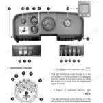
The parking brake warning light comes on when the parking brake is engaged and the ignition key is in the ON position. To clear the warning, the parking brake must be disengaged by pushing the parking brake switch into the DISENGAGE (RELEASE) position. If the parking brake is engaged and the machine is started, a horn will also sound (page 36).
How do you fix jcb Vibromax VM 132 – 200 D / PD vibrating excessively during transit and wheel lug nuts loosening after rough terrain use?
Inspect the wheels and verify tyre pressure is between 0.9 to 1.4 bar as shown on page 21. Torque all wheel nuts to the specified 560 to 600 Nm rating. Check for transport damage and review storage procedures on page 84 if the machine sits idle.
How do you fix total loss of drive motion requiring emergency recovery and manual bypass of the hydraulic drive system?
Open the multiple-function valve to disengage the brake system for transport as shown on page 53. After towing, reset the system and torque the bypass screw to 40 Nm. Torque the multiple-function valve main body to 90 Nm as directed on page 92 to prevent fluid leaks.
Is this JCB Vibromax VM 132 – 200 D / PD Operator Manual a digital download?
Instant PDF download. You get the full 110-page searchable Operator Manual immediately after payment. Open it on your laptop, tablet, or phone right in the shop.
Can I print specific sections of this JCB Vibromax VM 132 – 200 D / PD?
No restrictions at all. Print individual pages, full chapters, or the entire manual. The PDF is completely unlocked.
Does this manual have electrical diagrams?
Yes, an electrical wiring diagram is included to help trace the main circuits.
Reviews
There are no reviews yet.