


![John Deere 3320 3520 3720 Test and Adjustments Technical Manual [Compact Utility Tractors]](https://youfixthis.com/wp-content/uploads/2012/02/Manual_Download-300x300.jpg)
Factory Diagnosis, Operation and Test Technical Manual TM1552 For John Deere 7200 7400. Detailed step by step illustrations, instructions, diagrams for Systems Diagnosis, System Theory of Operation, Performance Testing, Tests and Adjustments, Operational Check, Operation, Unit Locations and Identification, Diagnostic Codes, Schematics and lot of other useful information.
PDF Manual:
Instant download – You will receive the link for download on your email immediately after payment.
Lifetime PDF and access to download (by request)
Compatible with Windows, Mac, IOS, Android and other systems
Searchable Text and Built-in index for instant information search
Bookmarks
Printable – pages or entire manual
Zoomable – detailed exploded diagrams, picture
Models
John Deere
7200
7400
Contents
SECTION —SAFETY INFORMATION
—Safety
SECTION —GENERAL INFORMATION
—Operational Checkout
—General Reference Information
—Test Equipment Calibration
SECTION —DIAGNOSTIC SERVICE CODES
—CCU
—HCU
—LHP
SECTION —OBSERVABLE SYMPTOMS
—Brakes
—Hitch
—Operator Station
—Hydraulics
SECTION —ENGINE
—General Information
SECTION —FUEL, AIR INTAKE AND ENGINE COOLING SYSTEMS
—Fuel/Air/Cooling System Theory of Operation
SECTION —ELECTRICAL SYSTEM
—Diagnostic Codes and Addresses
—Electrical System Information
—System Diagrams
—SubSystem Diagnostics
—Calibration and References
SECTION —TRANSMISSIONS
—Operational Checks
—POWRQUAD Diagnosis
A—SYNCROPLUS Diagnosis
—POWRQUAD Theory of Operation
A—SYNCROPLUS Theory of Operation
SECTION —DRIVE SYSTEMS
—Operational Checks
—Drive System Diagnosis
—Adjustments
—Theory of Operation
SECTION —STEERING AND BRAKES
—Tests and Adjustments
—Steering And Brakes Theory of Operation
SECTION —HYDRAULIC SYSTEM
—Operational Checks
—Hydraulic System Diagnosis
—Calibration and Adjustments
—Theory of Operation
SECTION —OPERATOR STATION
—Air Conditioning Operational Checks
—Air Conditioning System Diagnosis
—Air Conditioning Theory of Operation
SECTION —DEALER FABRICATED TOOLS
—Dealer Fabricated Tools
…
The parts to be coupled now have the same speed. Due to the continued shifting force of shift collar against synchronizer ring, the ring is turned back until shift collar teeth are in line with tooth gaps of synchronizer ring. At this moment the resistance is overcome which prevented further movement of shift collar. The shift collar can now move and mesh silently with the gear to be engaged. Shaft and gear are firmly coupled and the gear is engaged.
Should two teeth be opposite each other during engagement, the tapered teeth of the gear to be engaged will turn until teeth can engage in opposite gap.
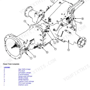
Drive shaft (B) is driven by the engine through flange (A), universal-jointed shaft (K) and torsion damper (J).
Drive shaft (B) is connected to clutch drum (C) by splines. Clutch disks (D) rotate with clutch drum (C), and their friction drives internally splined disks (G).
Internally splined disks (G) are rigidly attached to the clutch hub, which transmits the torque to the transmission by means of splines. The clutch is actuated by pressure acting on piston (H), which compresses the clutch disks.
The resulting friction enables the clutch to transmit torque from the engine to the transmission.


Reviews
There are no reviews yet.