


Part of the John Deere Repair Manuals.
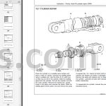
This is the complete John Deere factory repair manual (TM2070) for the 7220, 7320, 7420 and 7520 two-wheel-drive tractors. Across 2,476 pages it covers everything from pulling and rebuilding the PowerTech diesel to servicing the PowrQuad Plus and AutoPowr/IVT transmissions, tracing the full electrical system with wiring harnesses, and overhauling the hydraulic pumps, valves and rockshaft. Model-specific differences between the 7220/7320 and 7420/7520 are split into parallel sections throughout, so you work from the procedure that matches your serial number. Engine speeds, torque values and pressure test specs are printed at the point of use, not buried in an appendix.
What's Inside This John Deere 7220-7520 Repair Manual
| System | Pages | Key Topics |
|---|---|---|
| Safety | - | |
| General Information | Specifications, Tune-Up, Inspection Before Delivery | |
| Engine | Installing and Removing Components | |
| Fuel, Air Intake, Heating, Exhaust System | Speed Control, Fuel System, Air Intake System, Heating System, Cold-Weather Starting Aid, Exhaust System | |
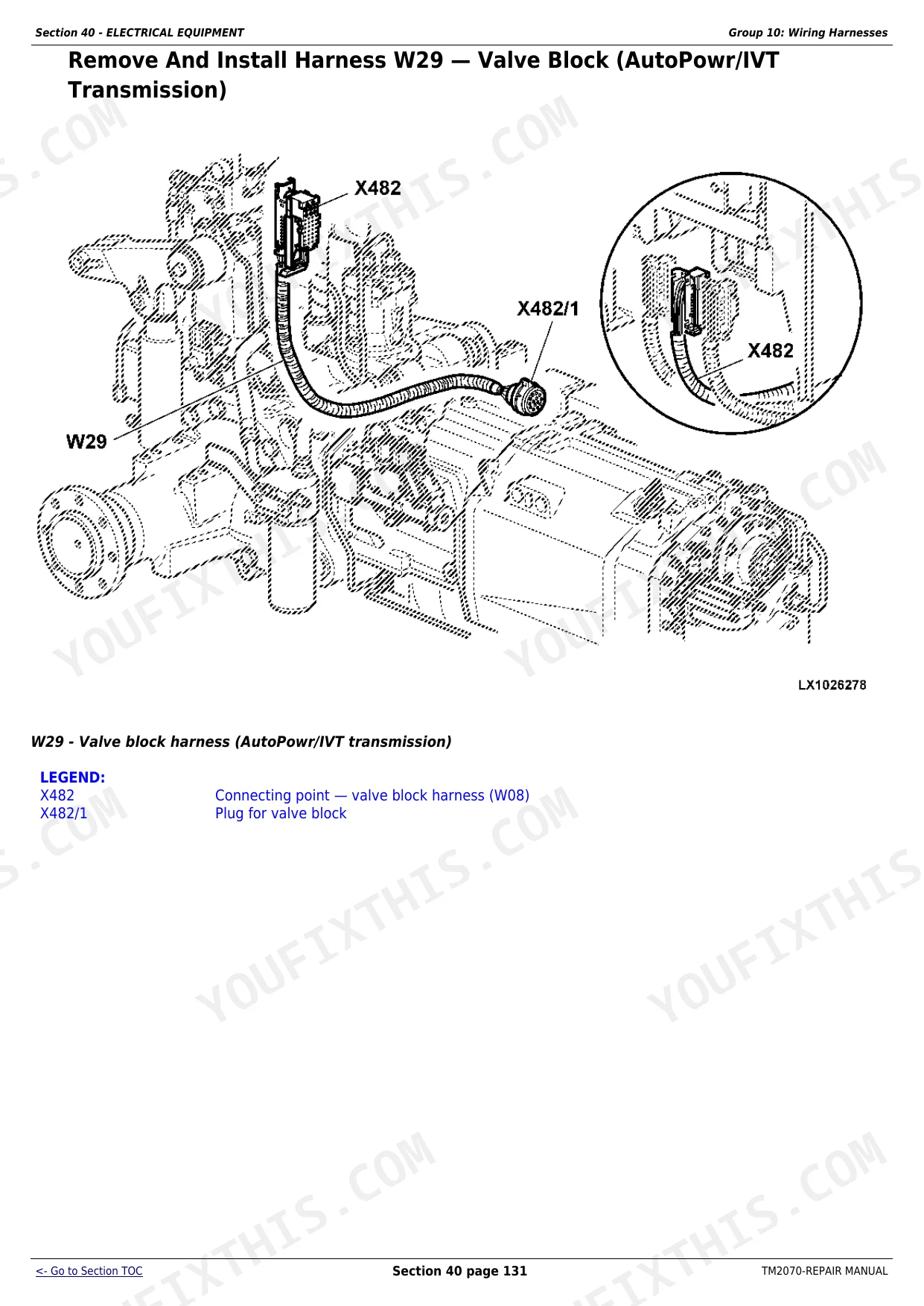
| Electrical Equipment | Electrical Connectors, Wiring Harnesses, Charging Current Circuit, Starting Circuit Current, Fuses, Relays and Connectors, Monitoring Systems, Electrical Components | |
| AutoPowr/IVT Transmission (7420, 7520) | Removing and Installing AutoPowr/IVT Transmission, Transmission Shifting Mechanisms, Input Housing, Output Housing, Assembling Intermediate Shaft | |
| AutoPowr/IVT Transmission (7320) | Removing and Installing AutoPowr/IVT Transmission, Transmission Shift Controls, Input Housing, Output Housing, Assembling Differential Drive Shaft | |
| PowrQuad and PowrQuad Plus Transmissions (7420, 7520) | Install and Remove Components, Transmission Shifting Mechanisms, PowrQuad Module, Creeper Transmission, Range Transmission | |
| PowrQuad and PowrQuad Plus Transmissions (7220, 7320) | Removal and Installation of Components, Transmission Shift Controls, PowrQuad Module, Creeper Transmission, Option Transmission, Range Transmission | |
| Drive Systems (7420, 7520) | Removal and Installation of Components, Universal Joint Shaft and Torsion Damper, FWD Clutch, Differential, Hydraulic Pump Drive, Final Drives, Hi-Crop Final Drive (7420), Rear PTO | |
| Drive Systems (7220, 7320) | Removal and Installation of Components, U-Jointed Shafts and Torsion Damper, Front-Wheel Drive Clutch, Differential, Hydraulic Pump Drive, Final Drives, Rear PTO Options, Front PTO | |
| Steering and Brakes | Hydrostatic Steering, Brake Valve, Rear Wheel Brakes | |
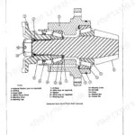
| Hydraulic System | Control Elements, Hydraulic Pump and Charge Pump, Valves, Rockshaft (7420, 7520), Rockshaft (7220, 7320), Additional Control Units and Reception Couplings, Independent Control Valve | |
| Miscellaneous | Remove and Install Components, Main Frame (7420, 7520), Main Frame (7220, 7320), Front and Rear Wheels, Axle Suspension of TLS Front Wheel Drive Axle | |
| Operator's Cab | Installing and Removing Components, Controls and Instruments, Air Conditioning System, Heating System, Seats, Cab Suspension, Components of the Electronic Hitch Control | |
| Special Tools (Dealer-Fabricated) | Dealer-Fabricated Special Tools for Transmission and Drive System Service |
Quick Reference Specifications
| Specification | Value | Page |
|---|---|---|
| 7220, 7320 | ||
| Rated engine speed | 2300 rpm | |
| 7420, 7520 | ||
| Rated engine speed | 2100 rpm | |
| All models | ||
| Slow idle (above 20 degrees C / 68 degrees F) | 850 plus or minus 10 rpm | |
| Slow idle (0 to 20 degrees C / 32 to 68 degrees F) | 875 plus or minus 50 rpm | |
| Fast idle (electronic actuation) | 2460 rpm (-10/+20) | |
| Cooling system test pressure | 50 to 60 kPa (0.5 to 0.6 bar; 7 to 8.7 psi) | |
| Engine mounting screws torque | 100 Nm (74 lb-ft) | |
| Front engine supports to main frame cap screws torque | 95 Nm (70 lb-ft) | |
| Universal joint shaft to input flange cap screws torque | 135 Nm (100 lb-ft) | |
John Deere 7220-7520 Common Problems This Manual Covers
Tractor locks into come-home mode and will not shift above a slow speed
This almost always traces to the 10-pin connector wiring or loss of supply voltage at the X404 plug pin 23. Pull the connector, inspect for corrosion, bent pins or damaged insulation, and repair the harness as described in the Electrical Equipment section. After the wiring repair, verify the fault code clears before returning the tractor to field work, because a recurring fault means the connector or harness segment needs full replacement, not just cleaning.
Manual Section: Electrical EquipmentEngine starts slowly or cranks but will not fire reliably in cold weather
Cold-start problems on these tractors usually come from a degraded glow plug circuit, low battery voltage, or a fuel system issue with the HPCR pump. The Fuel, Air Intake, Heating, Exhaust System section covers the cold-weather starting aid and the fuel system service procedure. Check the glow plug relay and battery connection condition first, then inspect the HPCR fuel pump for delivery pressure before condemning the injection circuit, since pump failure is the most common cause of hard starts that do not respond to standard cold-start assist.
Manual Section: Fuel, Air Intake, Heating, Exhaust SystemHydraulic system oil temperature warning appears or hydraulic functions feel sluggish under load
Hydraulic oil temperature fault code 334010.01 triggers when the transmission or hydraulic oil is below operating temperature during cold weather, or when actual oil temperature rises too high from restricted flow. After the cold-start case is ruled out, check the hydraulic oil level using the dipstick on the 7220 and 7320 or the sight glass on the 7420 and 7520, inspect the filter for contamination, and test the hydraulic pump output pressure as described in the Hydraulic System section to distinguish a flow restriction from a genuine overtemperature fault.
Manual Section: Hydraulic SystemAutoPowr/IVT transmission slips or produces a fault code during field operation
Slippage combined with a transmission fault code on the 7420 or 7520 typically points to internal clutch wear or a loss of hydraulic pressure to the transmission control circuit. The AutoPowr/IVT Transmission section for the 7420 and 7520 covers removal of the unit, disassembly of the input and output housings, inspection of the intermediate shaft assemblies and internal clutch packs, and the correct reassembly sequence with torque values so the repair holds up after reinstallation.
Manual Section: AutoPowr/IVT Transmission (7420, 7520)Frequently Asked Questions
What models does TM2070 cover and are the procedures different between them?
TM2070 covers the 7220, 7320, 7420 and 7520 two-wheel-drive tractors built from 2002 to 2007. The 7420 Hi-Crop variant is also included. Where procedures differ between the 7220/7320 and the 7420/7520, the manual splits them into parallel sections so you follow the one that matches your serial number. The transmission chapters are organized this way throughout.
How do I get the tractor out of come-home mode and back to normal operation?
Come-home mode is triggered by a fault in the AutoPowr/IVT transmission circuit, commonly a wiring fault at the 10-pin connector or loss of 12V at the X404 plug pin 23. The Electrical Equipment section covers the connector and harness repair procedure. Rotating relay K10 90 degrees or unplugging it resets diagnostic mode on most 7000-series machines, but the underlying fault must be repaired or it will return.
What are the key engine torque specs and RPM settings for these tractors?
Rated engine speed is 2300 rpm on the 7220 and 7320, and 2100 rpm on the 7420 and 7520. Slow idle runs at 850 rpm when ambient temperature is above 20 degrees C. Engine mounting screws torque to 100 Nm (74 lb-ft) and front engine support cap screws torque to 95 Nm (70 lb-ft). The General Information section lists these plus all additional assembly values.
Does this manual cover both the PowrQuad and AutoPowr/IVT transmissions?
Yes. The manual has dedicated chapters for each transmission type, further split by model. The PowrQuad and PowrQuad Plus chapters cover the 7420/7520 and the 7220/7320 separately, and the AutoPowr/IVT chapters do the same split. Each chapter covers removal, disassembly, internal inspection and reinstallation so you can rebuild the transmission in the field or at a shop.
Are wiring diagrams and hydraulic schematics included in TM2070?
Yes, both are included. The Electrical Equipment section covers the complete wiring harness layout, connector identification and circuit testing for the charging system, starting circuit, monitoring systems and all electronic components. The Hydraulic System section covers the pump, charge pump, control valves and rockshaft with pressure test specifications for diagnosing low-flow or leakage faults.
How quickly can I access this manual after?
You get a 2476-page searchable PDF (48 MB) that downloads instantly after checkout. Open it on your laptop, tablet, or phone, and bring it right to the shop floor.
Are there any print restrictions on this John Deere 7220, 7320, 7420, 7520?
No restrictions at all. Print individual pages, full chapters, or the entire manual. The PDF is completely unlocked.