


![John Deere 5200 5300 5400 5500 Diagnostic and Repair Technical Manual [Tractor] TM1520 April 2004](https://youfixthis.com/wp-content/uploads/2019/12/2020-09-11_11.11.45-300x300.jpg)
![John Deere 444D 544D 644D Operation and Tests Technical Manual [Wheel Loader]](https://youfixthis.com/wp-content/uploads/2012/02/Manual_Download-300x300.jpg)
Part of the John Deere Repair Manuals.
This is the John Deere factory Diagnosis and Tests service manual (TM2047) for the 7220, 7320, 7420 and 7520 tractors. It is the diagnostic and electrical testing volume - written for dealer technicians who need to find and confirm a fault before repairing it. The 5,627 pages cover observable symptom-based fault trees, step-by-step diagnostic trouble code procedures for all 14 electronic control units, hydraulic system pressure and flow tests with real measured specifications, fuel and cooling system tests, functional wiring schematics for both AutoPowr/IVT and PowrQuad-Plus transmission variants, ECU address tables for reading live sensor data, and a special tools reference. This volume is the companion to the Repair manual TM2070 - it does not cover teardown or torque specs for assembly, but gives you everything needed to test and confirm a failure before removing any parts.
What's Inside This John Deere 7220-7520 Manual
| System | Pages | Key Topics |
|---|---|---|
| Safety and General References | Safety Measures, Bolt and Cap Screw Torque Tables, Hydraulic Fitting Torque Values, How to Read a Functional Schematic, Wire Numbers and Color Codes, Seven Step Electrical Test Procedure | |
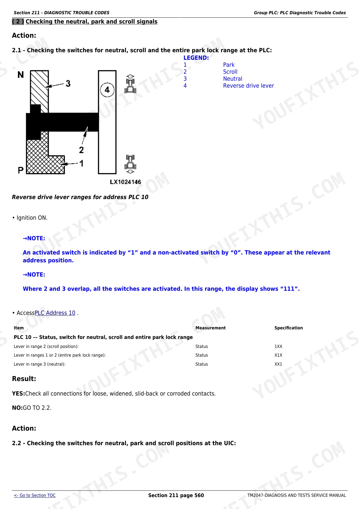
| Diagnostic Trouble Codes | Atc (ClimaTrak), Bcu (Basic Control Unit), Bif (Basic Informator), ECU (Engine Control Unit), Epc (PowrQuad-Plus), Jdl (JDLink), Plc (Park Lock), Prf (Performance Monitor), Sfa (MFWD and Cab Suspension), Sic (E-SCV/E-ICV), Ssu (AutoTrac), Tcu (AutoPowr/IVT), Tec (Tractor Equipment Controller), Uic (User Interface Controller) | |
| Observable Symptoms | Engine Symptoms, Electrical System Symptoms, Transmission Symptoms, Drive System Symptoms, Steering and Brake Symptoms, Hydraulic System Symptoms, Operator Cab Symptoms | |
| System Diagnostics - Electronics | CAN Bus Diagnostics, 29-Bit CAN Bus Checks, Data Bus System Verification | |
| Engine | Engine Wiring References, Preliminary Engine Tests, Dynamometer Test Procedure, Distinguishing Engine Control Units (Level 4 ECU / Bosch VP44 vs Lucas Injection) | |
| Fuel, Air Intake and Cooling Systems | Air Intake System Test, Cooling System Leak Test, Low-Temperature Circuit Flow Test (AutoPowr and PowrQuad Variants), Thermostat Opening Temperature Test, Viscous Fan Drive Test, Fuel Transfer Pump Check, Hand Throttle and Accelerator Pedal Adjustment | |
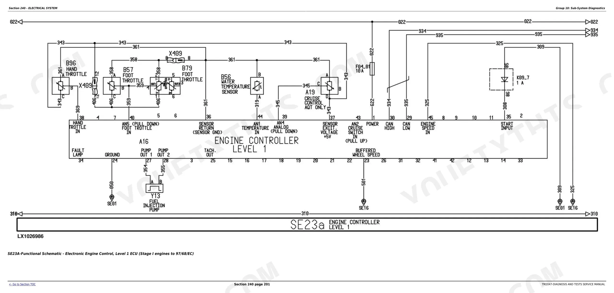
| Electrical System | Sub-System Diagnostics, Component Testing, Functional Schematics (AutoPowr/IVT and PowrQuad-Plus), Functional Schematics (Open Operator Station), Wiring Harnesses, Wiring Harnesses From Serial No. 12451 | |
| Electronic Control Units | General Operating Instructions, Accessing Addresses and DTCs, Data Bus Systems Diagnostics, CAN Bus Theory of Operation, Per-ECU Diagnostic Address Tables | |
| AutoPowr / IVT Transmission | Operational Checkout, Tests and Adjustments, Come Home Mode Diagnostics, Transmission Operation Theory | |
| PowrQuad and PowrQuad-Plus Transmissions | Introductory Checks, Operational Checkout, Tests and Adjustments, Transmission Operation | |
| Drive Systems | Operational Checks, Tests and Adjustments, Drive System Operation | |
| Steering and Brakes | Introductory Checks, Operational Checkout, Tests and Adjustments, Steering and Brake Operation | |
| Hydraulic System | Pfc Hydraulic System Load Check, Hitch Operational Checkout, SCV Operational Checkout, Hydraulic Pump Pressure and Delivery Rate Tests, Charge Pump Lube Oil Pressure, Ls Pressure Check, Rockshaft Valve Tests, Power Beyond Valve Adjustment, SCV Leak Tests, Pfc Hydraulic System Theory of Operation, Shuttle Valves, Priority Valve, Selective Control Valves | |
| MFWD | Operational Checkout, Tests and Adjustments, MFWD Operation | |
| Operator's Cab | Operational Checks, Tests and Adjustments, Cab System Theory of Operation | |
| Special Tools | Dealer-Fabricated Tools, Special Tools and Test Equipment List |
Quick Reference Specifications
| Specification | Value | Page |
|---|---|---|
| All models | ||
| Max PFC Hydraulic System Pressure | 19500-20500 kPa (195-205 bar / 2830-2970 psi) | |
| Min System Pressure (Standby) | 2800-3300 kPa (28-33 bar / 406-479 psi) | |
| Min LS (Load-Sensing) Pressure | 200-600 kPa (2-6 bar / 29-87 psi) | |
| Hydraulic Pump Min Delivery Rate | 100 L/min (26.4 gpm) | |
| Min Lube Oil Pressure (Charge Pump) | 100 kPa (1 bar / 14.5 psi) | |
| Cooling System Test Pressure | 50-60 kPa (0.5-0.6 bar / 7-8.7 psi) | |
| Expansion Tank Cap Opening Pressure | 70-90 kPa (0.7-0.9 bar / 10-13 psi) | |
| 7220, 7320, 7420 | ||
| EPC Enable Pressure (7220-7420) | 1400 kPa (14 bar / 203 psi) | |
| 7520 | ||
| EPC Enable Pressure (7520) | 1750 kPa (17.7 bar / 254 psi) | |
| 7220, 7320, 7420, 7520 Tier II engines | ||
| Fuel Transfer Pump Flow Rate (Tier II engine) | 100 L/hr (26.4 US gal./hr) | |
John Deere 7220-7520 Common Problems This Manual Covers
Tractor locks into come-home mode and will not drive normally in forward or reverse
Come-home mode is triggered by the TCU when it detects a critical fault in the AutoPowr / IVT transmission circuit. Start by reading the TCU diagnostic trouble codes in Section 211 (Group TCU) to identify the specific trigger code. Then follow the Section 253 operational checkout: check connector X404 for 12V supply at pin 23, inspect the wiring harness for open or intermittent circuits on the 10-pin connector, and confirm the TCU receives valid speed sender signals. Do not assume transmission mechanical failure until the electrical supply and sensor circuits are cleared by the test procedure.
Manual Section: Section 253 - AutoPowr / IVT TransmissionMultiple CAN BUS fault codes stored across BCU, BIF and other control units at the same time
Multiple simultaneous CAN BUS codes (BCU 000639.x, BIF 000639.02 and similar) point to a shared 29-bit CAN BUS problem rather than individual ECU failure - and the BCU/BIF notes explicitly flag that these codes are often stored accidentally during ignition key cycling. Go to Section 213 (System Diagnostics, Group 45) for the CAN BUS check procedure. Verify fuse F04/13 for the CAN BUS screen supply, check terminating resistors A14 and A15, and inspect shield lines 930 and 932 before replacing any control unit.
Manual Section: Section 240 - Electrical SystemHydraulic system stays in high-pressure mode with all valves in neutral instead of dropping to standby
When engine noise in neutral matches the noise with an SCV actuated, the PFC system is not dropping to standby (28-33 bar / 406-479 psi). Section 270 Group 10 load-check procedure confirms this symptom. Then use the hydraulic pump pressure and flow tests in Group 15 to check for a leak in the Load Sense circuit, a stuck priority valve in the main block, or a fault in the pressure-and-flow regulator. The test port locations are mapped in Reference 270-15-011, and the result table in Reference 270-15-013 narrows the fault to the pump or the circuit.
Manual Section: Section 270 - Hydraulic SystemEngine overheats or ECU 000110 coolant temperature DTCs are stored
Section 230 Group 15 starts with a pressure test of the cooling system at 50-60 kPa to find leaks, and confirms the expansion tank cap opens at 70-90 kPa. For overheating without a cap or leak fault, check the low-temperature circuit flow rate using Reference 230-15-075 (PowrQuad tractors) or 230-15-076 (AutoPowr tractors) to confirm the LTC coolant pump delivers adequate flow. The ECU 000110 code thresholds in Section 211 show the coolant sender voltage range so you can tell whether the sender is reading high or the coolant is genuinely hot.
Manual Section: Section 230 - Fuel, Air Intake and Cooling SystemsFrequently Asked Questions
Does this manual cover resetting come-home mode on the 7320 and 7420 AutoPowr transmission?
Yes. Section 253 covers the AutoPowr / IVT Transmission fully, including operational checkout and tests and adjustments for the TCU. The TCU diagnostic trouble code section in Section 211 lists each come-home mode trigger code with the specific test steps and wiring checks needed to confirm the fault and clear it. Connector X404, pin 23 (12V supply) is called out specifically as the first check when the tractor locks into come-home mode.
What diagnostic trouble code sections are covered in this manual?
Section 211 covers DTCs for all 14 electronic control units on the 7220-7520 platform: ATC (ClimaTrak), BCU (Basic Control Unit), BIF (Basic Informator), ECU (Engine Control Unit), EPC (PowrQuad-Plus), JDL (JDLink), PLC (Park Lock), PRF (Performance Monitor), SFA (MFWD and Cab Suspension), SIC (E-SCV/E-ICV), SSU (AutoTrac), TCU (AutoPowr/IVT), TEC (Tractor Equipment Controller) and UIC (User Interface Controller). Each entry includes the cause list, circuit reference and step-by-step test procedure.
What hydraulic test pressures and specs are in this manual?
Section 270 lists verified PFC hydraulic system specifications: max system pressure 195-205 bar (2830-2970 psi), standby pressure 28-33 bar (406-479 psi), min charge pump lube oil pressure 1 bar (14.5 psi), and min LS pressure 2-6 bar. The section also covers hydraulic pump delivery rate testing (min 100 L/min), test port locations, and the SCV leak rate limits at 150 bar for both load-check and non-load-check valve designs.
How do I access diagnostic addresses on the 7320 or 7420?
Section 245 covers the Electronic Control Units in detail, including the procedure for accessing diagnostic addresses and diagnostic trouble codes on each ECU. The manual explains how to read live address data - for example BCU Address 03 for engine speed sender status, BCU Address 32 for system voltage (should read 12.5-15.4V at 1500 rpm), or EPC Address 13 for enable switch pressure - so you can confirm sensor readings before replacing parts.
Is this the same as the John Deere 7220-7520 Repair manual TM2070?
No. These are separate volumes that work together. TM2047 is the Diagnosis and Tests manual - it covers fault-finding, DTC codes, electrical component testing, hydraulic test procedures and functional wiring schematics for the 7220, 7320, 7420 and 7520. TM2070 is the companion Repair manual and covers disassembly, component rebuild and torque specifications. The standard workflow is to use TM2047 to confirm the fault and isolate it to a component, then use TM2070 to repair or replace it.
How quickly can I access this manual after?
You get a 5627-page searchable PDF (88 MB) that downloads instantly after checkout. Open it on your laptop, tablet, or phone, and bring it right to the shop floor.
Are there any print restrictions on this John Deere 7220, 7320, 7420, 7520?
No restrictions at all. Print individual pages, full chapters, or the entire manual. The PDF is completely unlocked.


