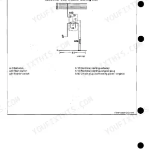
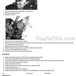
Part of the John Deere Repair Manuals.
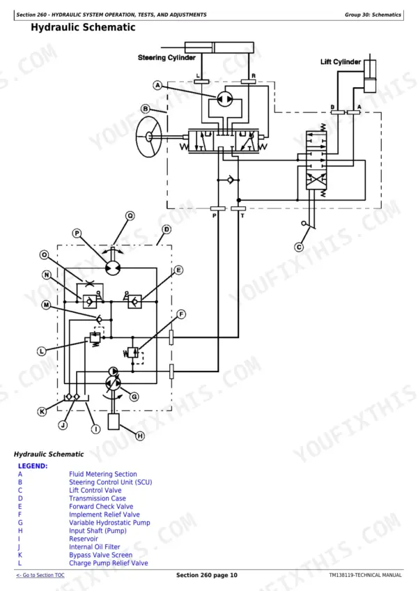
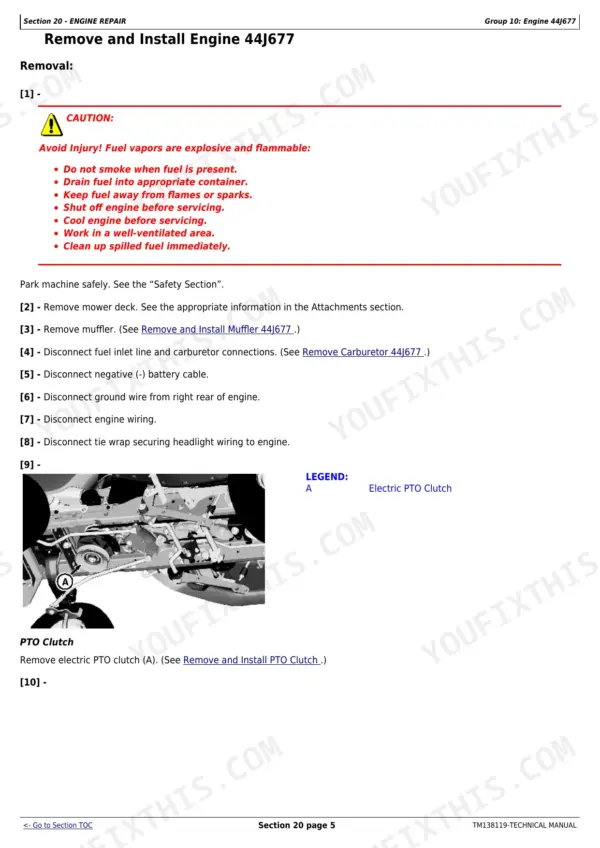
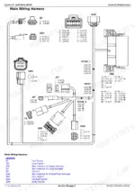
This 752-page John Deere X330 Technical Manual (OEM #TM138119) covers the full Select Series lawn tractor lineup: X330, X350, X354, X370, X380, X384, X390, and X394. You get wiring diagrams for every model's harness, hydraulic schematics for the lift and drive systems, plus a dedicated DTC section that turns a blinking dash light into an actual answer instead of a guessing game. Set the blower housing screws to 9 N·m (80 lb-in) and torque the muffler flange nut on the 44J677 engine to 22 N·m, straight from the factory table, not a forum thread. Your key switch fuse pulls 15A; know that before you start swapping parts that aren't the problem. One tractor down for a wiring gremlin costs more than this manual ever will. Bookmarked by section and searchable by keyword, so you can jump straight to Group 30 Schematics without flipping through 750 pages by hand.
What's Inside This John Deere X330 to X394 Series Manual
| System | Pages | Key Topics |
|---|---|---|
| General Information | 8-41 | Safety (Recognize Safety Information, Understand Signal Words, Replace Safety Signs, Handle Fluids Safely, Avoid Fires, Prepare for Emergencies, Prevent Battery Explosions, Prevent Acid Burns, Wear Protective Clothing, Avoid High-Pressure Fluids, Avoid Heating Near Pressurized Fluid Lines, Service Machines Safely, Use Proper Tools, Park Machine Safely, Support Machine Properly, Use Proper Lifting Equipment, Work in Clean Area, Protect Against High Pressure Spray, Illuminate Work Area Safely, Work in Ventilated Area) |
| Engine Repair | 42-258 | Engine 44J677, Engine FS600V, Engine FS651V |
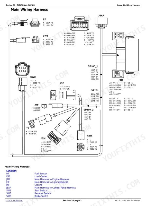
| Electrical Repair | 259-267 | Wiring Harness |
| Power Train Repair | 268-311 | Transaxle, Drive Belts, Clutch, Shafts, Hydrostatic Drive |
| Steering and Brake Repair | 312-346 | Steering, Brakes |
| Hydraulic Repair | 347-362 | Hydraulic Pump, Control Valve, Cylinders, Hoses, Reservoir |
| Attachment Repair | 363-397 | Mower Deck, Blades, Spindles, Front Attachments, Drive Belts |
| Operator’S Station Repair | 398-407 | Operator’s Station |
| Miscellaneous Repair | 408-418 | Wheels, Tires, Frame, Fuel Tank, Fasteners |
| Engine Operation, Tests, and Adjustments | 419-519 | Engine Component Location, Theory of Operation, Diagnostic Tests, Adjustments, Specifications |
| Electrical Operation, Tests, and Adjustments | 520-624 | Electrical Component Location, Theory of Operation, Diagnostic Tests, Adjustments, Specifications |
| Power Train Operation, Tests, and Adjustments | 625-662 | Power Train Component Location, Theory of Operation, Diagnostic Tests, Adjustments, Specifications |
| Steering and Brake Operation, Tests, and Adjustments | 663-699 | Steering & Brake Component Location, Theory of Operation, Diagnostic Tests, Adjustments, Specifications |
| Hydraulic System Operation, Tests, and Adjustments | 700-724 | Hydraulic Component Location, Theory of Operation, Diagnostic Tests, Adjustments, Specifications |
| Attachment Operation, Tests, and Adjustments | 725-747 | Attachment Component Location, Theory of Operation, Diagnostic Tests, Adjustments, Specifications |
| Miscellaneous Operation, Tests, and Adjustments | 748-749 | Miscellaneous Component Location, Theory of Operation, Diagnostic Tests, Adjustments, Specifications |
| Service Tools and Kits | 750-752 | Service Tools, Dealer-Fabricated Tools, Test Kits |
Quick Reference Specifications
| Specification | Value | Page |
|---|---|---|
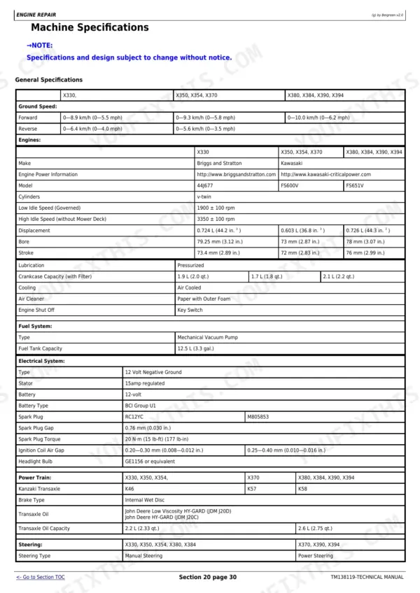
| Muffler Flange Nut, 44J677 | 22 N·m (16 lb-ft) | p. 50 |
| Blower Housing Screws | 9 N·m (80 lb-in) | p. 52 |
| Fuel Shutoff Solenoid | Y1 | p. 265 |
| Key Switch Fuse | 15 A | p. 265 |
| Power Port Fuse | 10 A (Option) | p. 265 |
| Ignition Coil | T1 | p. 265 |
| Seat switch wire | 400D and 400J wires | p. 526 |
| Fuel Solenoid | Digital Output (HSD) | p. 522 |
| Fuse F1 | 15A | p. 529 |
| Fuse F2 | 10A | p. 529 |
| Key Switch | terminals L (lights on position), A2, and B | p. 526 |
| ICC replacement | replaced as an assembly | p. 535 |
John Deere X330 to X394 Series Common Problems This Manual Covers
John Deere X330-X394 Select Series engine runs fine then suddenly dies for no reason
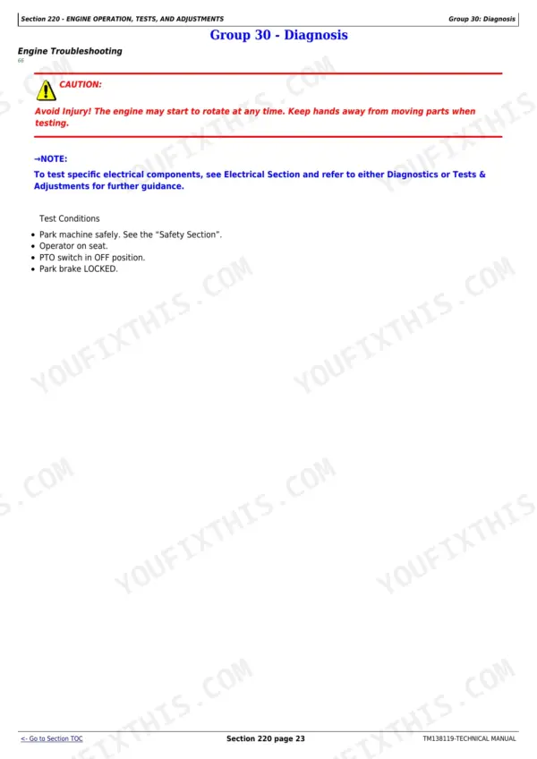
Check the engine troubleshooting chart for erratic running and unexpected shutdown. Test the seat switch wires 400D and 400J on page 526 for continuity, then measure fuel solenoid coil resistance across terminals A-A; expect 33 ohms ±15% per page 563. If the ICC control unit fails, replace it as a complete assembly per page 535.
Manual Section: Engine TroubleshootingEngine fails to start, no crank or click when key is turned
Pull and inspect fuse F3 (20A) on page 527, then check fuses F1 (15A) and F2 (10A) on page 529 for continuity. Verify the 7.5A F4 fuse on page 537 hasn't blown. Test key switch continuity between terminals B-A1 and L-A2 on page 569 with a multimeter; replace the switch if it fails to show continuity in the run position.
Manual Section: Electrical Operation, Tests, and Adjustments p. 527Intake and exhaust valves carboned up and sticking after only 130 hours
Drain the fuel tank and carburetor if the mower sat with old or contaminated fuel; carbon on the valve stems is usually diet-related, not a parts defect. Follow the valve service procedure, and torque the cylinder head bolts to 25 N·m (220 lb-in) per page 43. Reinstall the spark plug to 22 N·m per page 471.
Manual Section: Engine RepairRusty water spraying out of the engine compartment during every cold morning startup
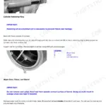
Remove the blower housing to inspect the flywheel for surface rust; moisture condensing overnight on a bare flywheel is the usual cause, not a coolant leak. Wipe the flywheel dry and coat lightly with anti-corrosion spray before reinstalling. Torque the blower housing screws to 9 N·m (80 lb-in) per page 52 during reassembly.
Manual Section: Engine Repair p. 52Mower deck pulleys wearing out fast, belt squealing and slipping while cutting grass
Inspect the mower deck drive belt and pulleys for glazing or uneven wear, then check tire pressure and deck level using the diagnosis and adjustment procedures beginning on page 725. Verify the PTO clutch cap screw is torqued to 81 N·m as specified on page 269; a loose PTO clutch lets the belt slip and speeds up pulley wear.
Manual Section: Attachment Operation, Tests, and Adjustments p. 725Frequently Asked Questions
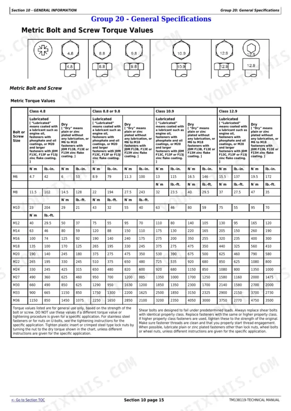
What are the torque specifications for mower blade bolts on John Deere Select Series X330, X350, X354, X370, X380, X384, X390, X394?
For 42M Mowers, the blade nut torque is 88 N·m (65 lb-ft). For 42A, 48A, and 54A Mowers, the blade cap screw torque is 68 N·m (50 lb-ft). These specifications ensure proper blade installation. p. 388
What do the error codes mean on John Deere X330, X350, X354, X370, X380, X384, X390, X394?
The manual provides a 'DTC Quick Reference' table that lists various E-codes, their descriptions, causes, and recovery actions. For example, E1000 indicates 'Crank time exceeded' due to the crank time maximum interval being exceeded, with a recovery action to 'Cycle key switch'. p. 548
How do I troubleshoot starting issues on John Deere X330, X350, X354, X370, X380, X384, X390, X394?
To troubleshoot starting issues, refer to the 'Engine Troubleshooting' section, which includes procedures for 'Engine Does Not Crank' and 'Engine Cranks but Will Not Start'. Additionally, specific procedures for 'Starting Motor Does Not Rotate' and 'Starting Motor Rotates Slowly' are provided to diagnose starter-related problems. p. 441
What are the replacement specifications for the Electronic Control Unit (ECU) on John Deere X330, X350, X354, X370, X380, X384, X390, X394?
The Instrument Cluster Controller (ICC), which functions as the ECU, has no serviceable components and must be replaced as an assembly if defective. The manual states that the controller is the component least likely to fail and should only be replaced if diagnostic procedures indicate it is necessary. p. 535
How quickly can I access this John Deere X330–X394 Series manual after buying?
A 752-page Technical Manual in searchable PDF format, available the moment you complete checkout. View on computer, tablet, or phone, with no shipping wait.
Am I able to print pages from this John Deere X330–X394 Series manual?
Yes. Many mechanics print the section they need for their own shop and bring it to the bench.
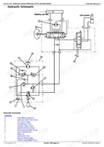
Does this John Deere X330–X394 Series manual include hydraulic schematics?
Yes, a hydraulic system diagram is included showing the main circuit layout.