


![John Deere CS and CX Repair Manual [Gator Light Duty Utility Vehicles]](https://youfixthis.com/wp-content/uploads/2016/06/2017-04-03_10-55-59-300x300.jpg)
Part of the John Deere Repair Manuals.
This is the John Deere TM1677 Technical Manual for the 4200, 4300, and 4400 Compact Utility Tractors, the same 742 page service manual John Deere wrote for its own technicians. It covers the 3TNE78A, 3TNE84, and 3TNE88 diesel engines fitted across the three models.Twelve sections take you from safety and torque specifications through the diesel engine, the full electrical system with schematics and wiring harnesses, and all three drivetrains: gear, hydrostatic, and SyncReverser. Steering, brakes, hydraulics, and final drive repairs are covered with component locations, theory of operation, tests, and step by step disassembly.Use it to diagnose a no start, trace a wiring fault, set clutch and brake adjustments, or rebuild a transmission with correct clearances and torque values. The file is a downloadable, searchable PDF with 637 bookmarks, ready to print any page you need at the bench.
What's Inside This John Deere 4200, 4300, 4400 Manual
| System | Pages | Key Topics |
|---|---|---|
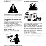
| Safety | 4-8 | Recognize Safety Information, Handle Fluids Safely-Avoid Fires, Use Care in Handling and Servicing Batteries, Use Care Around High-Pressure Fluid Lines, Use Safe Service Procedures |
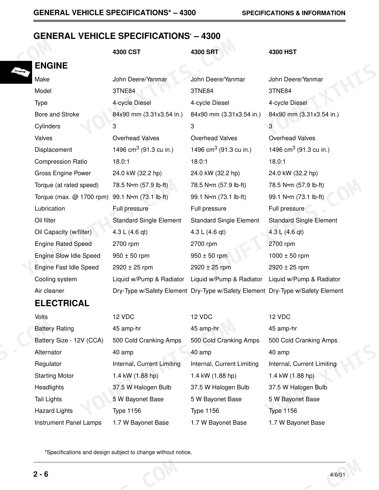
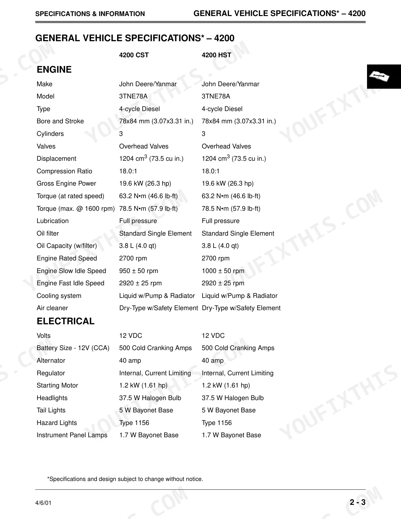
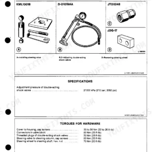
| Specifications and Information | 9-32 | General Vehicle Specifications, Inch Fastener Torque Values, Metric Fastener Torque Values, O-Ring Seal Service Recommendations, Diesel Fuel Specifications |
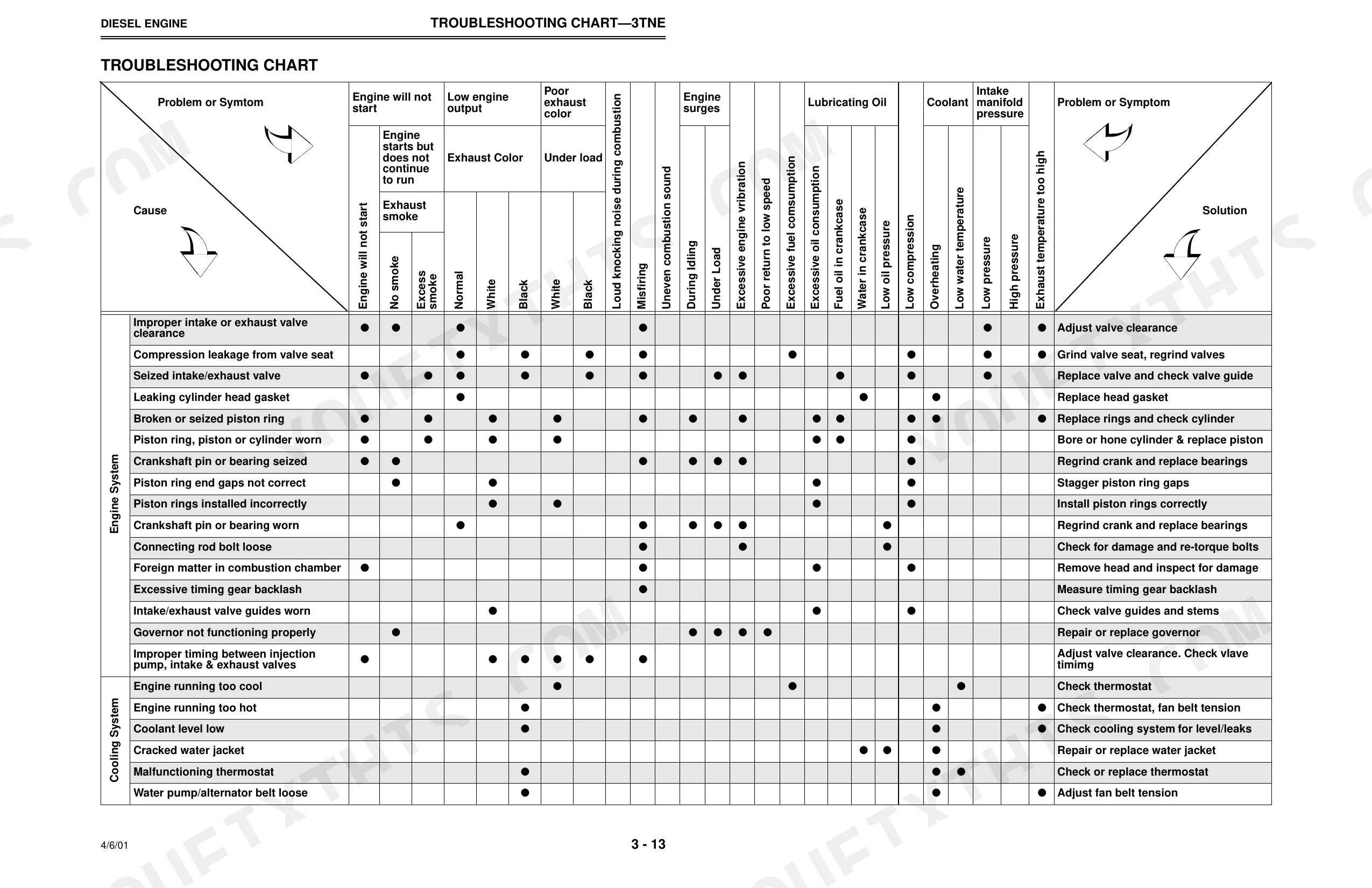
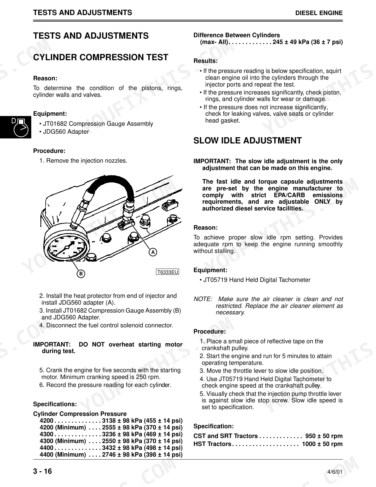
| Diesel Engine | 33-116 | Cylinder Head, Valves, Connecting Rod, Piston, Piston Pin, Piston Rings, Cylinder Bore, Crankshaft |
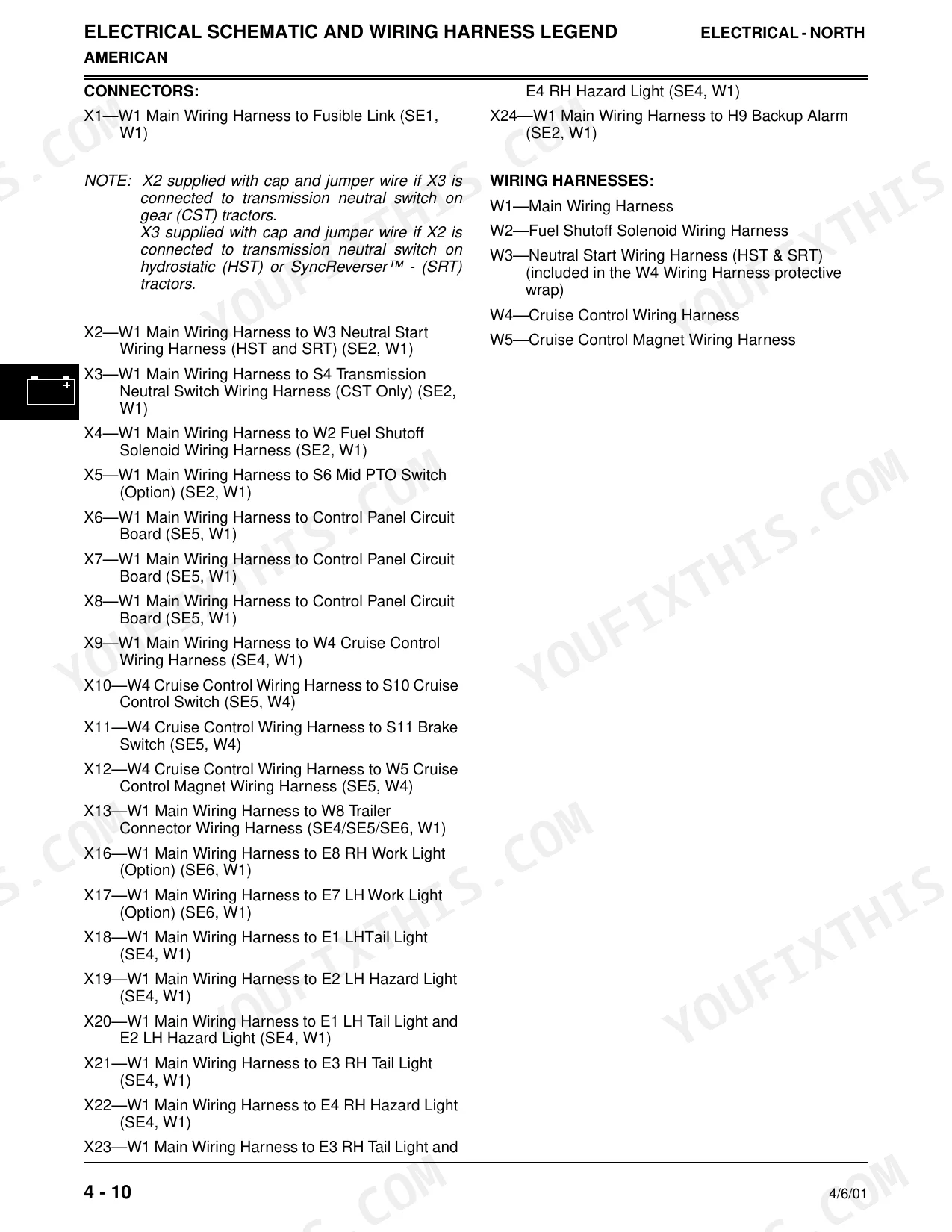
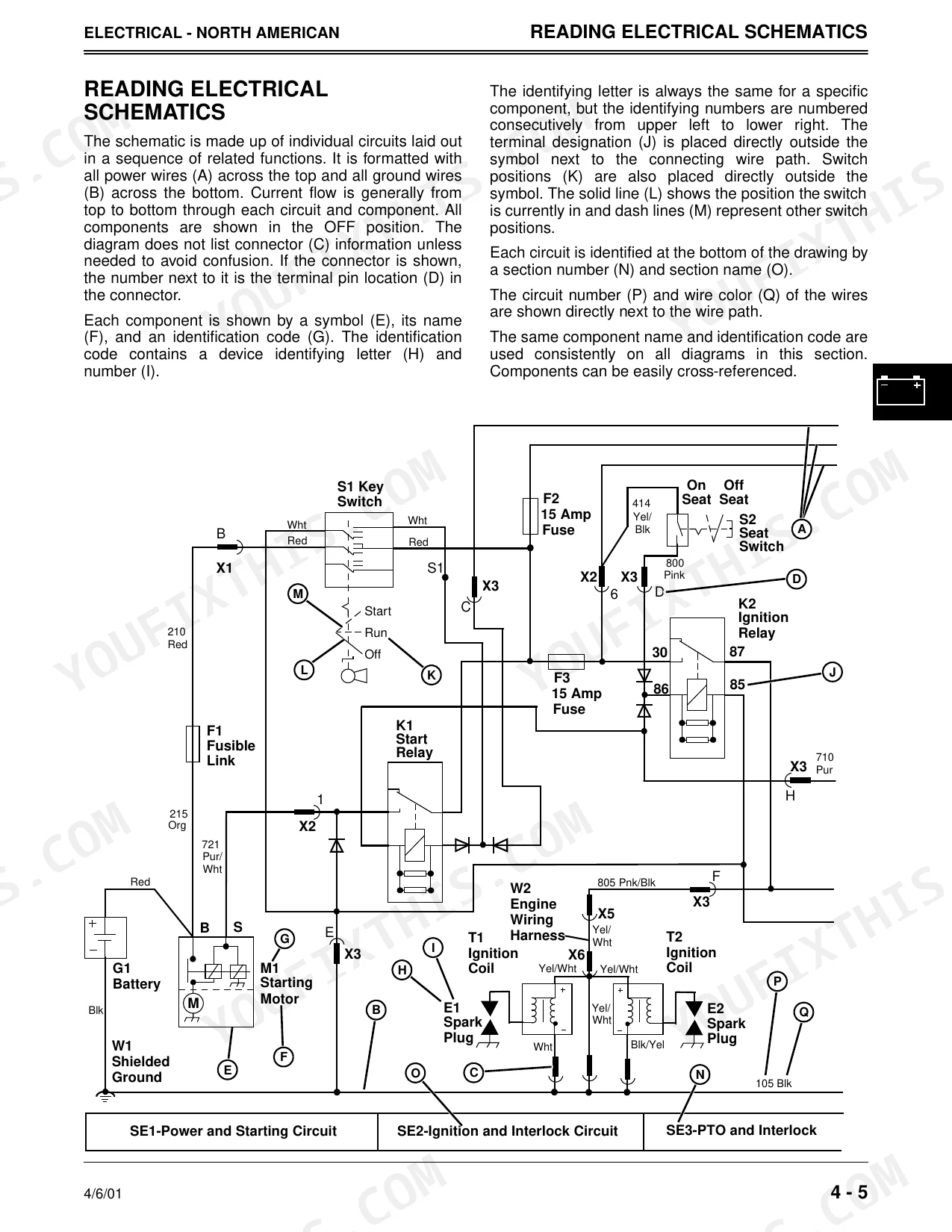
| Electrical | 117-360 | Reading Electrical Schematics, Theory and Diagnostic Information, Specifications (North American and European), Schematics and Wiring Harnesses, Troubleshooting |
| Gear Power Train | 361-412 | Specifications, Component Location, Clutch Adjustment, Tractor Splitting (Front), Collar Shift (CST) Traction Clutch Disassembly, 3-Speed Transmission Disassembly |
| Hydrostatic Power Train | 413-460 | Specifications, Component Location, Theory of Operation, Hydrostatic Pump Pressure Test, Hydrostatic Transmission Disassembly, Hydrostatic Motor Disassembly |
| Syncreverser™ Power Train | 461-506 | Specifications, Theory of Operation, SRT Clutch Linkage Adjustment, Syncreverser Traction Clutch Disassembly, Clutch Shimming Procedure, 4-Speed Transmission Disassembly |
| Final Drive Power Train | 507-606 | Axle Shaft, Brake, Range Shift Transmission, Differential Lock, Drive Shaft, MFWD Axle, MFWD Final Drive, MFWD Differential |
| Steering | 607-622 | Specifications, Steering Component Location, Theory of Operation, Troubleshooting Chart, Steering System Test, Tie Rod Disassembly and Assembly |
| Brakes | 623-650 | Specifications, Component Location, Brake Theory of Operation, Troubleshooting Chart, Brake Pedal Adjustment, Brake Disassembly and Inspection |
| Hydraulics | 651-702 | Hydraulic Specifications, Rockshaft Component Location, SCV Valve Component Location, Hydraulic Pump Component Location, Hydraulic System Bleed Procedure |
| Miscellaneous | 703-730 | Torque Specifications, Three Point Hitch, Roll Over Protective Structure (ROPS), Fuel Tank, Cab Repair, PTO Gearbox Removal |
Quick Reference Specifications
| Specification | Value | Page |
|---|---|---|
| 4300, 4400 | ||
| Cylinder Head Bolts Torque (Lubricating Oil Applied) | 85 - 91 N•m (63 - 67 lb-ft) | p. 41 |
| 4200 | ||
| Front Wheel Mounting Bolts | 68 N•m (50 lb-ft) | p. 109 |
| All Models | ||
| Relay Coil Resistance | approximately 80 ohms | |
| Relay Replacement Condition | If continuity is NOT correct, replace relay | |
| Fuel Shutoff Solenoid Voltage | 12 VDC | p. 124 |
| Fuel Shutoff Solenoid Pull-in Voltage | 6.8 VDC | p. 124 |
| Wheel Sealant | John Deere Sealant TY6304 | p. 511 |
| Wheel Bearing Seal Replacement Condition | Replace as required if damaged or worn | p. 561 |
| Park Brake Switch Plunger Travel for Engagement | about 3 mm (1/8 in.) from bottoming | |
John Deere 4200, 4300, 4400 Common Problems This Manual Covers
Intermittent no start condition
These tractors can crank but fail to start intermittently, often traced to the fuel shutoff solenoid or a start-circuit fault. The Electrical section gives the solenoid voltage specs and the diagnostic path to isolate it.
Manual Section: Section 4 - ELECTRICAL p. 117Corroded relays cause electrical faults
Relays and their connections corrode with age and cause intermittent electrical operation, from gauges to accessories. Use the schematics and troubleshooting charts in the Electrical section to test and replace the affected relay.
Manual Section: Section 4 - ELECTRICAL p. 117Front steering knuckle oil leaks
The front steering knuckle seals wear over time and start to weep gear or hydraulic oil. The Steering section covers component location, tie rod service, and knuckle disassembly and reassembly.
Manual Section: Section 9 - STEERING p. 607Parking brake light stays on
Owners report the parking brake light staying lit, or only clearing when the lever is moved. The Brakes section covers pedal and lever adjustment plus the switch circuit so you can correct it.
Manual Section: Section 10 - BRAKES p. 623Rear housing cracks at backhoe mounts
On units run with a backhoe, loose mounting bolts let the brackets move and can crack the rear housing near the mounting points. The Final Drive Power Train section documents the housing and its disassembly for inspection and repair.
Manual Section: Section 8 - Final Drive Power Train p. 507Brittle plastic hood and panels crack
The plastic hood and body panels become brittle with age and crack or break. The Miscellaneous section covers cab and body repair along with the ROPS and related bodywork.
Manual Section: Section 12 - MISCELLANEOUS p. 703Frequently Asked Questions
Which tractors does this manual cover?
It is the John Deere TM1677 Technical Manual for the 4200, 4300, and 4400 Compact Utility Tractors, covering all three models and their 3TNE78A, 3TNE84, and 3TNE88 diesel engines.
Does it include wiring diagrams and schematics?
Yes. The Electrical section runs the full theory, schematics, and wiring harnesses for the 4200, 4300, and 4400, plus troubleshooting charts to trace faults through the circuits. p. 117
What is the cylinder head bolt torque?
For the 4300 and 4400, the cylinder head bolts torque to 85 to 91 N·m (63 to 67 lb-ft) with lubricating oil applied. The Diesel Engine section lists the head and fastener torque values. p. 33
Does it cover the hydrostatic transmission?
Yes. The Hydrostatic Power Train section covers theory of operation, pump pressure testing, and full disassembly of the hydrostatic pump and motor, alongside separate sections for the gear and SyncReverser drivetrains. p. 413
What format is this John Deere 4200, 4300, 4400 manual in?
Immediate download of the complete 742-page searchable Technical Manual. Open it on any device: laptop at your desk or phone in the field.
Can I print specific sections of this John Deere 4200, 4300, 4400 manual?
Absolutely. No DRM or copy protection. Print the whole manual or just the pages you need. Any home or office printer works.
Are electrical wiring diagrams included in this John Deere 4200, 4300, 4400?
Included. The John Deere 4200, 4300, 4400 Technical Manual covers complete wiring harness diagrams, electrical circuits, and connector pinouts.


Reviews
There are no reviews yet.