
Part of the John Deere Repair Manuals.
This 478-page John Deere X700, X720, X724, X728 Technical Manual (OEM #TM2349) covers Select Ultimate Series tractors from the Electrical system down to the last brake linkage adjustment, and yes, it's the John Deere x720 technical manual pdf you've been hunting for instead of a forum thread. Inside you get full wiring schematics and harness routing for the Electrical section, hydrostatic power train diagnostics, and a hydraulics system breakdown that actually shows you where the pressure drops. Set oil pressure to 276 kPa (40 psi) minimum at 1250 rpm, and keep the battery charging temp at 16°C (60°F) or you're just cooking the plates. No more pulling the hood on a guess because the dash light came on. It's bookmarked for jumping straight to Engine, Electrical, or Brakes, and it opens fine on a phone propped on the fender while your hands are still dirty.
What's Inside This John Deere X700, X720, X724, X728 Manual
| System | Pages | Key Topics |
|---|---|---|
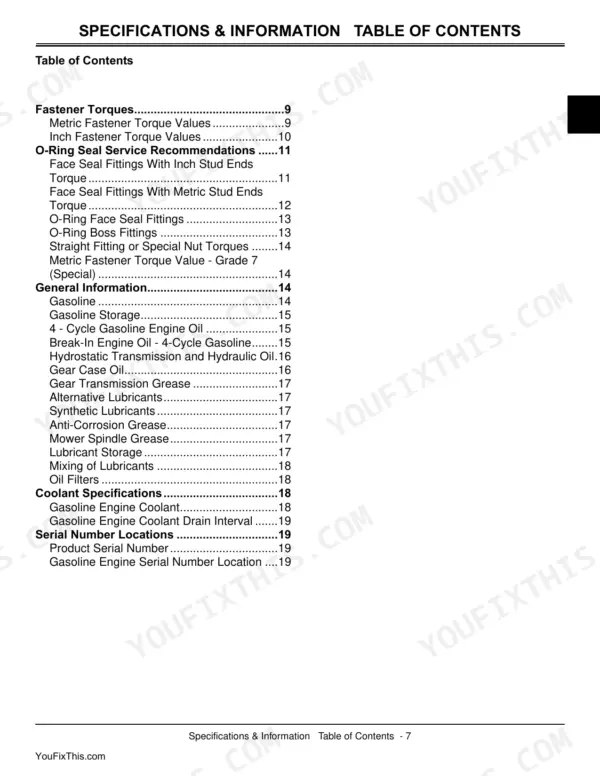
| Introduction | 3-4 | Table of Contents, Specifications and Information, Identification Numbers, Tools and Materials, Component Location, Theory of Operation |
| Safety | 5-10 | - |
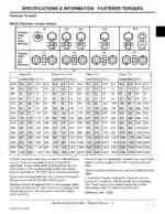
| Specifications & Information | 11-24 | Fastener Torques, O-Ring Seal Service Recommendations, General Information, Coolant Specifications, Serial Number Locations |
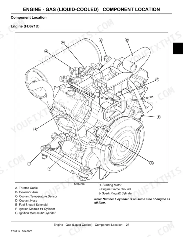
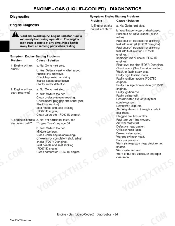
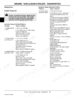
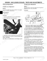
| Engine - Gas (Liquid-Cooled) | 25-102 | Specifications, Component Location, Theory of Operation, Diagnostics, Tests and Adjustments, Repair |
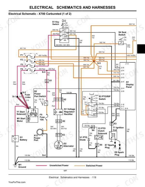
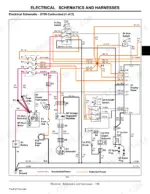
| Electrical | 103-236 | General Information, Component Location, Schematics and Harnesses, Operation and Diagnostics |
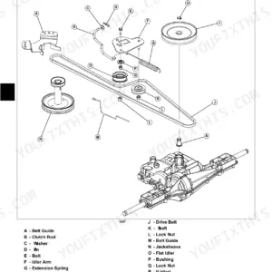
| Power Train - Hydrostatic | 237-338 | Hydrostatic Power Train and MFWD Final Drive Component Location, Front Axle Gear Case and Assembly (MFWD), Foot Control and Shift Lever Linkage, Oil Cooler, Control Arm and Damper, Differential Lock Linkage, Charge Pump Removal and Disassembly, Directional Control Valves, Hydrostatic Pressure Relief Valve, Drive Shaft |
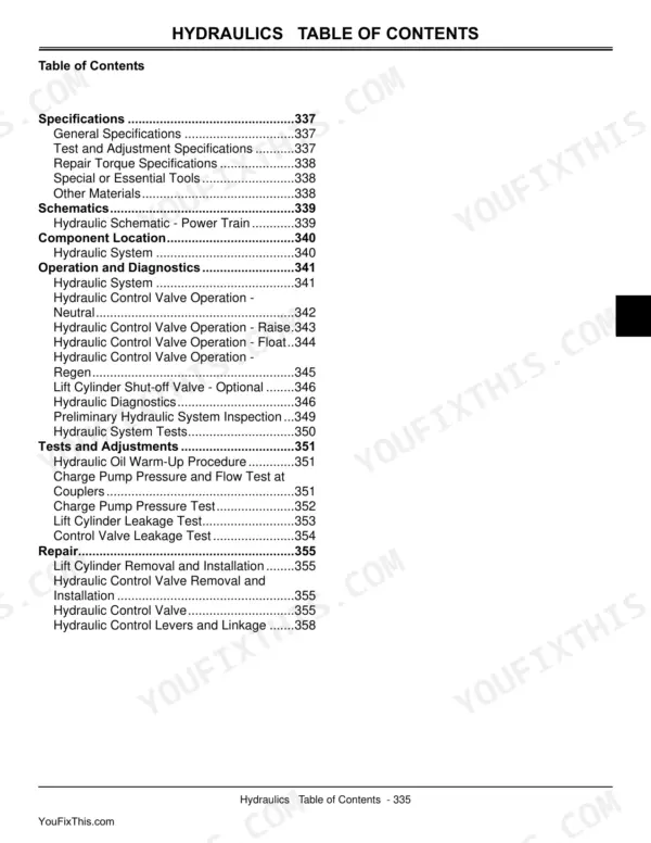
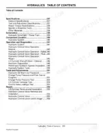
| Hydraulics | 339-362 | Hydraulic Schematic (Power Train), Hydraulic System Component Location, Hydraulic Control Valve Operation (Neutral, Raise, Lower), Diagnostics, Test and Adjustment Specifications, Repair Torque Specifications |
| Steering | 363-392 | Steering Components (Front Wheel Steer and All Wheel Steer), All Wheel Steer Rear Axle, Steering System Operation, Steering Valve Operation (Neutral, Turning, Manual), Tests and Adjustments, Repair |
| Brakes | 393-406 | General Specifications, Brake System Component Location, Brake System Operation, Brakes Diagnostics, Brake/Differential Linkage Adjustment, Brakes Removal and Installation |
| Attachments | 407-458 | 48, 54 and 62-Inch Mower Deck Diagnosis, 45 Loader Diagnosis, Adjusting Cutting Height and Mower Deck Level, Mower Deck Wheels, PTO Generator (Alternator, Control Panel, Gear Box Components), Wire Color Chart and Common Circuit Tests |
| Miscellaneous | 459-470 | Headlights Adjustment, Hood Removal and Installation, Fuel Tank Removal and Installation, Fuel Pump/Fuel Gauge Sensor Removal and Installation |
Quick Reference Specifications
| Specification | Value | Page |
|---|---|---|
| Battery temperature for charging | 16°C (60°F) | p. 6 |
| Oil Pressure (Minimum at 1250 rpm) | 276 kPa (40 psi) | p. 27 |
| Air Cleaner | Dual Element replaceable paper | p. 27 |
| Oil pressure switch (O) warning light activation pressure | 98 kPa (14.2 psi) | p. 36 |
| Engine Oil Pressure Switch: Switch Opening Pressure | 98 kPa (14.2 psi) | p. 112 |
| Starter Type | Solenoid Shift | p. 111 |
| Fuel Pump Relay Control (Ground) | K-460 Yel | p. 210 |
| Solenoid Valve Armature | 22 N•m (195 lb-in.) | p. 295 |
| 48-Inch Mower Deck: Blade Height | 6 mm (0.25 in.) Higher in Rear | p. 419 |
| 54-Inch Mower Deck: Blade Height | 6 mm (0.25 in.) Higher in Rear | p. 419 |
John Deere X700, X720, X724, X728 Common Problems This Manual Covers
John Deere X700 Ultimate Series engine repeatedly shuts off or won't restart after running for a while
Check the fuel pump relay ground circuit on page 210; verify continuity on the K-460 Yel wire. Pull the connector at the relay and inspect for corrosion or a loose crimp. Clean contacts with electrical cleaner, reseat the connector, and confirm 12V (page 111) reaches the relay coil with the key on.
Manual Section: Electrical p. 210PTO disengages and mower deck loses power after 10 to 30 minutes of operation
Let the PTO clutch cool for several minutes before diagnosing; a hot clutch coil trips thermal protection. Remove the shield (cap screws torque to 54 N·m/40 lb-ft, page 285) and check the solenoid valve armature torque against the 22 N·m (195 lb-in.) spec on page 295. Test coil resistance and replace the clutch if it fails cold.
Manual Section: Power Train - Hydrostatic p. 295Starter solenoid clicks repeatedly but engine won't turn over when key is turned to start
Verify battery voltage reads 12V (page 111) at rest before chasing the solenoid. Remove both cable terminals, wire-brush corrosion off the posts and clamps, and check for green buildup under the insulation. Charge in a location above 16°C (60°F) per page 6, since cold batteries deliver less cranking amperage. Reinstall, torque terminals snug, and retest for a solid click.
Manual Section: Electrical p. 111Severe vibration through the deck and seat only when the PTO is engaged during mowing
Pull each blade and check the cutting edge against the 0.40 mm (0.016 in.) wear limit on page 234; a bent blade shakes the whole deck. Spin each spindle by hand feeling for play or grinding, and replace worn bearings. Torque the blade cap screw to 68 N·m (50 lb-ft) per page 112, then recheck idler pulleys for looseness.
Manual Section: Attachments p. 234Engine overheats or loses power under heavy mowing in tall, thick, or wet grass conditions
Shut down and let the engine cool, then blow accumulated grass and chaff off the cooling fins and screen with compressed air. Pull the dual-element paper air filter and check it against the not-plugged condition on page 42; replace if clogged. Verify oil pressure holds above 276 kPa (40 psi) minimum per page 27, and confirm the fan belt isn't slipping.
Manual Section: Engine - Gas (Liquid-Cooled) p. 42Frequently Asked Questions
What are the torque specifications for John Deere X720 engine bolts?
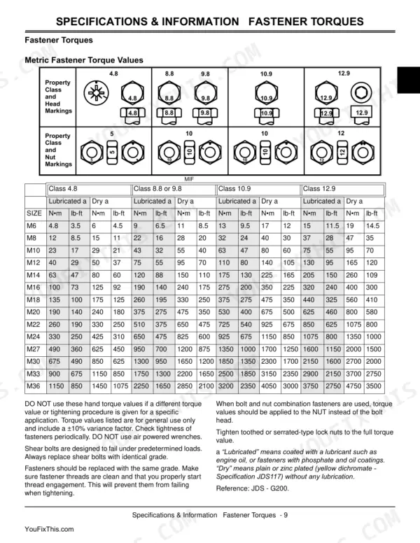
The manual provides various torque specifications for engine components. For instance, Cylinder Head Bolts (Silicone Sealant Applied) should be tightened to 27 N•m (20 lb-ft). Other examples include Spark Plug torque at 25 N•m (221 lb-in.) and Rocker Arm Bracket Mounting Bolts at 22 N•m (195 lb-in.). p. 29
What do error codes mean on John Deere X700 series?
The Display Code Chart provides meanings for various error codes. For example, the code 'brAHE' indicates that the brake pedal needs to be depressed, and the fault cause is 'S8 brake switch OK'. The code 'crAnH' means to turn the key switch to start, with the fault cause being 'S1 key switch OK'. p. 109
How to reset the oil pressure indicator on John Deere X724?
The oil pressure indicator light operates automatically. It illuminates when engine oil pressure is at or below 98 kPa (14.2 psi) and turns off when the engine starts and oil pressure increases above this threshold. There is no manual reset procedure for this indicator. p. 185
How to reset the battery discharge light on John Deere X728?
The battery discharge light is an automatic indicator that illuminates when the battery is not receiving a sufficient charge from the charging circuit. It will turn off once the charging circuit is functioning correctly and supplying adequate current to the battery. There is no manual reset procedure for this light. p. 186
What are the replacement specifications for PTO clutch assembly?
When inspecting the PTO clutch assembly, if the clearance measures 2.7 mm (0.106 in.) or more between the inner steel plate and the bottom of the clutch gear/hub, the PTO clutch plates should be replaced. The PTO brake pin, piston, springs, and O-Rings must be replaced as a set. p. 303
What format is this John Deere X700–X728 Series manual in?
You get a 478-page searchable PDF that downloads instantly after checkout. Open it on your laptop, tablet, or phone, and bring it right to the shop floor.
Is this John Deere X700–X728 Series Technical Manual printable?
Yes, print as many copies as you want, and there are no restrictions. Many mechanics print the section they need and bring it to the shop floor.







Reviews
There are no reviews yet.