
![John Deere 744K Repair Manual [Wheel Loader] TM10683](https://youfixthis.com/wp-content/uploads/2012/02/Manual_Download-300x300.jpg)
Part of the John Deere Repair Manuals.
This is TM110919, the September 2014 factory repair manual for the John Deere 9460RT, 9510RT, and 9560RT track tractors. It is a pure teardown and rebuild book: pulling the 13.5 L engine, splitting the power shift transmission, rebuilding the steering differential carrier and outboard planetaries, and servicing the track frame, tension cylinder, and suspension. You get component removal and installation steps, repair procedures, and torque values, including bolt and fitting torque charts up front. Be clear on what it is not: there are no wiring schematics, no hydraulic schematics, and no fault code lists. This is the book for when the machine is apart on the shop floor, not for chasing electrical gremlins.
What's Inside This John Deere 9460RT, 9510RT, 9560RT Repair Manual
| System | Pages | Key Topics |
|---|---|---|
| General Information | 9-88 | Safety Information, Metric and Unified Inch Bolt and Screw Torque Values, Fitting Torque Charts, Glossary of Terms |
| Engine | 89-109 | Component Removal and Installation, Engine Repair |
| Fuel, Air, and Cooling Systems | 110-249 | Diesel Fuel System, Air Intake System, Engine Cooling System, Exhaust System |
| Electrical | 250-534 | Charging Circuit, Starting Circuit, Relays, Fuses, Solenoids, And Switches, Monitoring Systems and Sensors |
| Power Shift Transmission (Pst) | 535-579 | Component Removal and Installation, Transmission Repair, Transmission Cleanup |
| Drive Systems | 580-652 | Drive Shafts, PTO Clutch, PTO Drop Box |
| Rear Axle Assembly | 653-885 | Outboard Planetary Final Drive, Outboard Planetary Service Brakes, Steering Differential Carrier, Input Pinion Housing |
| Steering and Brakes | 886-1058 | Steering Column, Steering Pump, Steering Motor, Brakes |
| Hydraulics | 1059-1176 | Hydraulic Pump, Axle Lubrication Pumps, Filter Housings and Control Valves, Hitch |
| Miscellaneous | 1177-1235 | Hood and Side Panels, Platform, Frames, Hitch Frame and Drawbar |
| Operator Station | 1236-1362 | Cab Removal and Installation, HVAC, Air Suspension Seat, Armrest |
| Track Frame and Components | 1363-1494 | Tracks, Tension Cylinder and Accumulator, Track Frame, Track Suspension |
| Dealer Tools | 1495-1585 | Dealer Fabricated Tools |
Quick Reference Specifications
| Specification | Value | Page |
|---|---|---|
| Engine Lift Bracket Cap Screws Torque | 120 N.m (90 lb-ft) | p. 90 |
| Engine Mounts-to-Frame Cap Screws Torque | 325 N.m (240 lb-ft) | p. 90 |
| Front Mount-to-Engine Cap Screws Torque | 300 N.m (220 lb-ft) | p. 90 |
| Damper-to-Flywheel Cap Screws Torque | 101 N.m (75 lb-ft) | p. 90 |
| Brake Pedal Travel Leak-Check Limit | 33 mm (1.3 in.) in 10 seconds max | p. 1046 |
| Hitch Surge Relief Valve Pressure | 22800 to 23800 kPa (228 to 238 bar; 3307 to 3452 psi) | p. 1148 |
| Track Alignment Lock Plate Cap Screws Torque | 130 N.m (95 lb-ft) | p. 1380 |
John Deere 9460RT, 9510RT, 9560RT Common Problems This Manual Covers
Brake pedal travels too far or brakes feel spongy
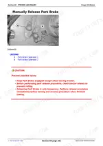
Stop the engine, wait at least 10 seconds, then apply the brake pedal for 5 seconds and release, then apply and hold while shutting off the engine. If pedal travel is greater than 33 mm (1.3 in.) in 10 seconds, that is the manual's own threshold for checking the brake circuit for leakage rather than just bleeding it again.
Manual Section: Steering and Brakes - Brakes p. 1046Hitch surges, jerks, or loses pressure under load
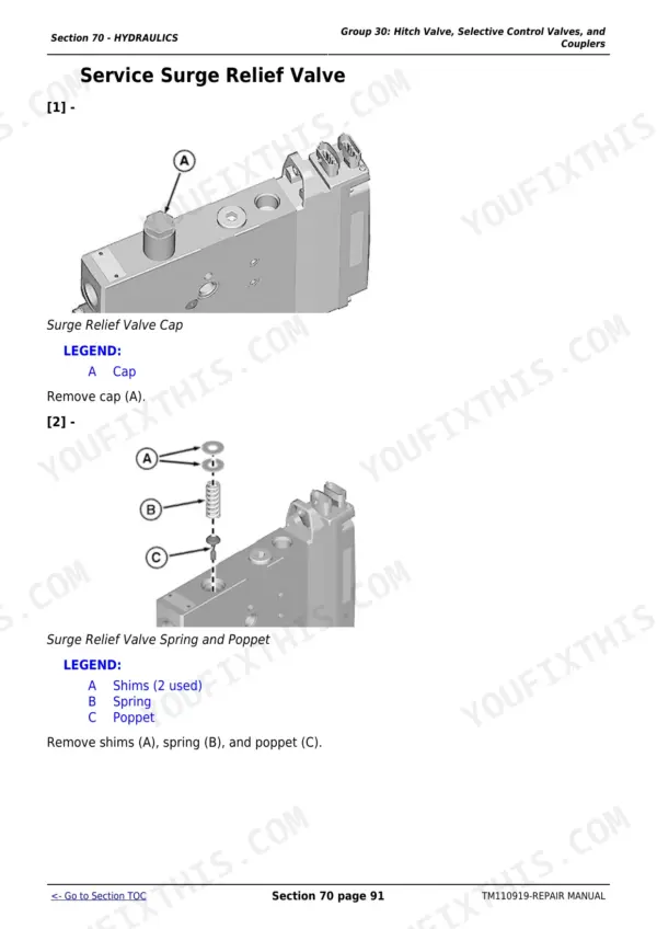
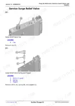
Connect the D01019AA hand pump to the hitch valve port and operate it to check pressure. A healthy surge relief valve reads 22800 to 23800 kPa (228 to 238 bar; 3307 to 3452 psi); outside that range, add or remove shims under the surge relief valve spring cap or repair the valve rather than replacing the whole hitch valve.
Manual Section: Hydraulics - Hitch Valve, Selective Control Valves, and Couplers p. 1148Track runs to one side and guide lugs get hot
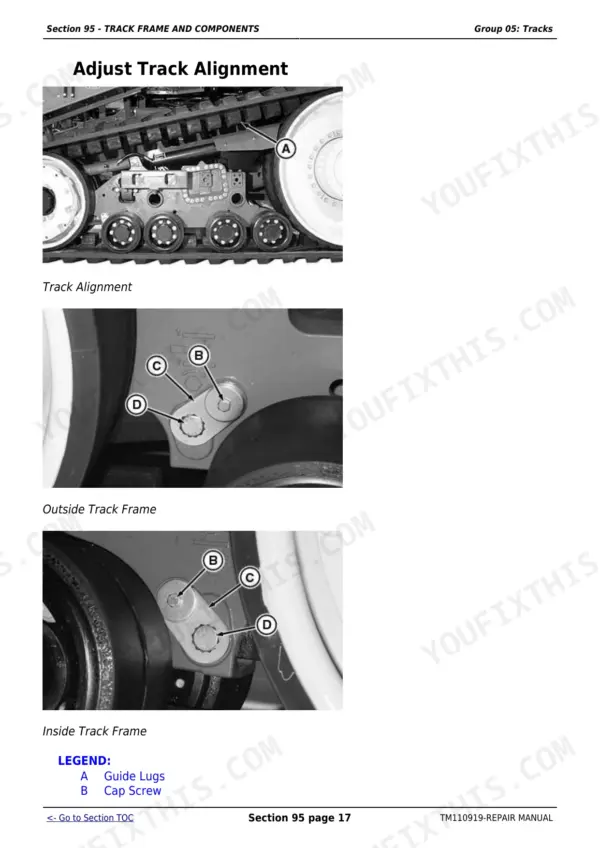
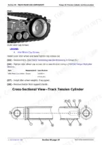
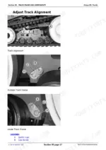
Loosen the special cap screw on the side you want the track to move toward and tighten the opposite one, then reinstall the retainer lock plates and torque the lock plate cap screws to 130 N.m (95 lb-ft). Let the guide lugs cool first since a track that has been running to the outside gets hot enough to burn you.
Manual Section: Track Frame and Components - Tracks p. 1379Engine mounting bolts or the lift bracket work loose after service
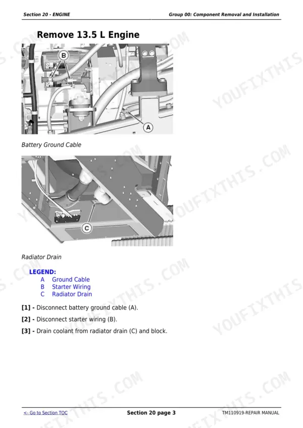
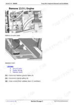
Reinstall to the printed torques for the 13.5 L engine rather than guessing: mounts-to-frame cap screws 325 N.m (240 lb-ft), front mount-to-engine cap screws 300 N.m (220 lb-ft), engine lift bracket cap screws 120 N.m (90 lb-ft), and damper-to-flywheel cap screws 101 N.m (75 lb-ft).
Manual Section: Engine - Component Removal and Installation p. 90Frequently Asked Questions
What models and edition does this Repair Manual cover?
This is the John Deere TM110919 Repair Manual (September 2014) for the 9460RT, 9510RT and 9560RT track tractors, exactly the model range printed on the cover. p. 1
Does this manual cover fault codes or diagnostic trouble codes?
No. This Repair Manual has zero fault-code or DTC content anywhere in it. It is a teardown, rebuild and torque-spec book, not a diagnostic manual. p. 1
Does it include wiring diagrams or electrical schematics?
No. The Electrical section covers connectors, charging and starting circuits and monitoring systems, but there are no wiring schematics in this Repair Manual. p. 250
What engine is in these tractors?
All three models (9460RT, 9510RT, 9560RT) share the same 13.5 L engine, per the printed torque specifications for its mounts, lift bracket and damper. p. 90
Does this manual cover the track undercarriage and tension system?
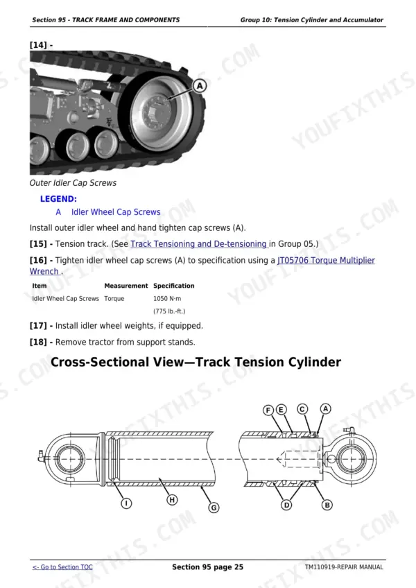
Yes. Section 95 covers the track frame, track alignment adjustment, and the tension cylinder and accumulator, including removal, disassembly and rebuild. p. 1363







