


Part of the John Deere Repair Manuals.
This is the John Deere factory repair manual (TM1744) for the 450H, 550H, and 650H H-Series crawler dozers. Across 2,083 pages it covers every repairable system on these machines: the PowerTech 4045T turbocharged diesel and all its auxiliary systems, the dual-path electronic hydrostatic transmission and final drives, the complete track and undercarriage, the main hydraulic system with pump and valve teardown, and the full electrical system with wiring harnesses and instrument diagnostics. The bulldozer blade, control linkage, and blade hydraulic circuits each have their own dedicated sections. It is the same information a John Deere dealer technician works from, with torque values, fluid capacities, and test pressures called out so a repair is done to spec the first time.
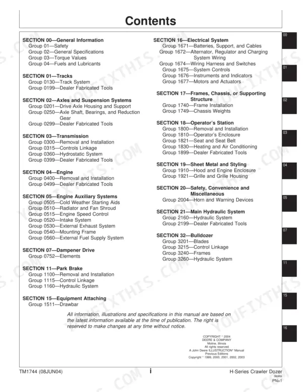
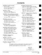
What's Inside This John Deere 450H-650H Repair Manual
| System | Pages | Key Topics |
|---|---|---|
| General Information | Safety, General Specifications, Torque Values, Fuels and Lubricants | |
| Tracks | Track System Removal and Adjustment, Track Tension, Carrier Rollers, Dealer Fabricated Tools | |
| Axles and Suspension Systems | Drive Axle Housing and Support, Axle Shaft, Bearings and Reduction Gear | |
| Transmission | Removal and Installation, Controls Linkage, Hydrostatic System Service and Testing | |
| Engine | Engine Removal and Installation, PowerTech 4045T 4-Cylinder Diesel | |
| Engine Auxiliary Systems | Cold Weather Starting Aids, Radiator and Fan Shroud, Engine Speed Control, Intake System, Exhaust System, External Fuel Supply System | |
| Dampener Drive | Dampener Drive Elements | |
| Park Brake | Removal and Installation, Control Linkage, Hydraulic System, Wet Multiple-Disk Brake | |
| Equipment Attaching | Drawbar | |
| Electrical System | Batteries, Support and Cables, Alternator and Charging System Wiring, Wiring Harness and Switches, System Controls, Instruments and Indicators, Motors and Actuators | |
| Frames and Chassis | Frame Installation, Chassis Weights | |
| Operator's Station | Removal and Installation, Operator's Enclosure, Seat and Seat Belt, Heating and Air Conditioning | |
| Sheet Metal and Styling | Hood and Engine Enclosure, Grille and Grille Housing | |
| Main Hydraulic System | Hydraulic System Removal, Testing, And Repair, Pump and Valve Service, Horn and Warning Devices | |
| Bulldozer | Blades, Control Linkage, Frames, Blade Hydraulic System |
Quick Reference Specifications
| Specification | Value | Page |
|---|---|---|
| 550H, 550H-LGP | ||
| Rated Power at 2200 rpm | 63 kW (84 hp) SAE net | |
| Maximum Net Torque at 1200 rpm | 372 N.m (276 lb-ft) | |
| Hydraulic System Pressure | 20 685 kPa (3000 psi) | |
| Hydraulic System Flow Rate | 56.8 L/min (15 gpm) at 2200 rpm | |
| Transmission Type | Dual-path, electronic-controlled, hydrostatic drive, infinitely variable | |
| 550H, 550H-LGP, 650H, 650H-LGP | ||
| Engine Oil Capacity (Including Filter) | 14 L (15 qt) | |
| Fuel Tank Capacity | 178 L (47 gal) | |
| Cooling System Capacity | 15.5 L (16 qt) | |
| Hydraulic Reservoir Capacity (Including Filter) | 32 L (8.5 gal) | |
| Transmission Reservoir Capacity (Including Filter) | 43 L (11.3 gal) | |
| Final Drive Capacity (Each Side) | 8.5 L (9 qt) | |
| 550H | ||
| SAE Operating Weight, 550H | 7620 kg (16,800 lb) | |
| 650H | ||
| SAE Operating Weight, 650H | 8391 kg (18,500 lb) | |
John Deere 450H-650H Common Problems This Manual Covers
Hydraulic hoses chafing and leaking at track-frame routing points
Inspect the full hose runs against the illustrations in the Main Hydraulic System section and compare clamp positions to the factory routing drawings. Re-route any hose that shows surface abrasion, replace the chafed section, and reinstall clamps at the specified anchor points. Simply patching or wrapping the hose without correcting the contact point will cause the failure to recur within a few hundred hours, so correct routing is the permanent fix.
Manual Section: Main Hydraulic SystemTrack sag out of specification causing accelerated undercarriage wear
Measure sag at the mid-point of the top run with the machine on level ground and compare it to the specification in Group 0130. Add grease to the track adjuster to reduce sag or bleed grease to increase it. If the adjuster has reached its travel limit the carrier rollers, bushings, and track links need to be measured against the worn service limits in the Track System group before deciding whether to rebuild or replace undercarriage components.
Manual Section: TracksLoss of drive on one or both tracks from hydrostatic system fault
Check transmission fluid level and condition first. Then use the pressure test points specified in the Hydrostatic System group (Group 0360) to measure charge pressure, forward and reverse working pressure on each drive path, and servo control pressure. A charge-pressure reading below specification points to a worn charge pump or relief valve; asymmetric working pressures on one side point to that path's piston pump or motor. The controls linkage check in Group 0315 should precede any pump removal to rule out a simple sensor or solenoid fault.
Manual Section: TransmissionIntermittent instrument panel faults or warning lights with no obvious cause
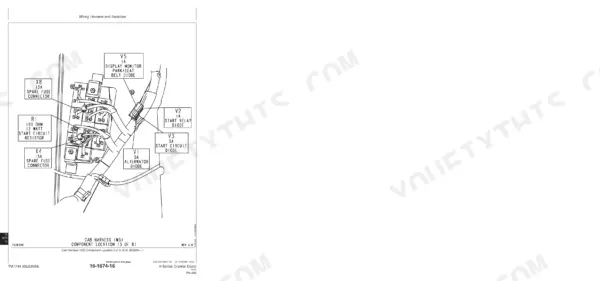
On these machines corrosion at the ground straps and connector pins near the undercarriage is the most common root cause of phantom instrument faults. The Wiring Harness and Switches section (Group 1674) and Instruments and Indicators section (Group 1676) provide connector pin-out tables and voltage test procedures so you can test each circuit at the connector rather than guessing at harness segments. Clean and re-tension any corroded connectors before condemning modules or gauges.
Manual Section: Electrical SystemFrequently Asked Questions
How do I diagnose a hydrostatic transmission failure on a John Deere 450H or 550H dozer?
Start by checking the transmission reservoir level and fluid condition. The Transmission section covers pulling test pressures on each drive-path circuit so you can tell whether the pump is the culprit or a control valve is stuck. Confirm the electronic control linkage is getting a signal before pulling components, and always note whether the failure is on one track side or both, which points you toward the individual pump or a shared pressure-reducing valve.
What are the fluid capacities and service intervals for a John Deere 550H crawler dozer?
Engine oil with filter is 14 L (15 qt); fuel tank holds 178 L (47 gal); cooling system takes 15.5 L (16 qt); the hydraulic reservoir holds 32 L (8.5 gal); the transmission reservoir holds 43 L (11.3 gal); and each final drive takes 8.5 L (9 qt). The Fuels and Lubricants section in Group 04 lists the correct fluid grades and drain intervals for each system.
How do I adjust track tension on a John Deere 450H, 550H, or 650H dozer?
Track sag is set with a grease-filled track adjuster accessible from the track frame. The Tracks section (Group 0130) gives the correct sag measurement and the procedure for adding or relieving grease to reach it. On worn undercarriages the adjustment bottoms out quickly, which means it is time to inspect carrier rollers and track bushings for wear beyond service limits.
What does it mean when a John Deere 550H dozer develops hydraulic leaks at the hoses?
Hoses rubbing against each other or against frame edges work through their outer cover over time and eventually leak or rupture. The Main Hydraulic System and Bulldozer hydraulic sections show the correct routing and clamp positions for each line. Always re-route hoses that show chafe marks rather than just wrapping them, because the contact point will recur.
Does this manual cover the wiring harness and electrical system on the 450H, 550H, and 650H?
Yes. Section 16 covers batteries and cables, the alternator and charging system, the wiring harness and switch repair, system controls, instrument panel and gauges, and motors and actuators. Connector and splice repair procedures are included so you can chase down intermittent faults without replacing entire harnesses.
What format is this John Deere 450H manual in?
Immediate download of the complete 2083-page searchable Repair (125 MB). Access it on any device, from a laptop at your desk to a phone in the field.
Can I print pages of this John Deere 450H manual for my own shop?
Yes. Many mechanics print the section they need for their own shop and bring it to the bench.







Reviews
There are no reviews yet.