


Part of the John Deere Repair Manuals.
Built around John Deere's own TM1575, this 1,124-page manual carries the 8100, 8200, 8300, 8400, 8110, 8210, 8310, and 8410 through factory-level repair. It covers exploded views, from the Power Shift Transmission out to both MFWD axle versions, step-by-step procedures, and specifications spanning engine, electrical, hydraulics, drive systems, steering, brakes, and cab. Torque your MFWD wheel hub cap screws to 610 N•m (450 lb-ft), drop to 310 N•m (228 lb-ft) on 2WD hubs, and set the solenoid plate cap screw at 18 N•m (159 lb-in.). No more guessing fastener values off a forum post. Everything is bookmarked and keyword-searchable, so on an 8410 or any of its siblings you can open it on a tablet, walk to the machine, and start wrenching.
What's Inside This John Deere 8100–8410 Repair Manual
| System | Pages | Key Topics |
|---|---|---|
| General Information | - | Group 05 Safety, Group 10 General Information, Recognize Safety Information, Handle Fluids Safely, Avoid Fires, Prevent Battery Explosions, Prepare for Emergencies |
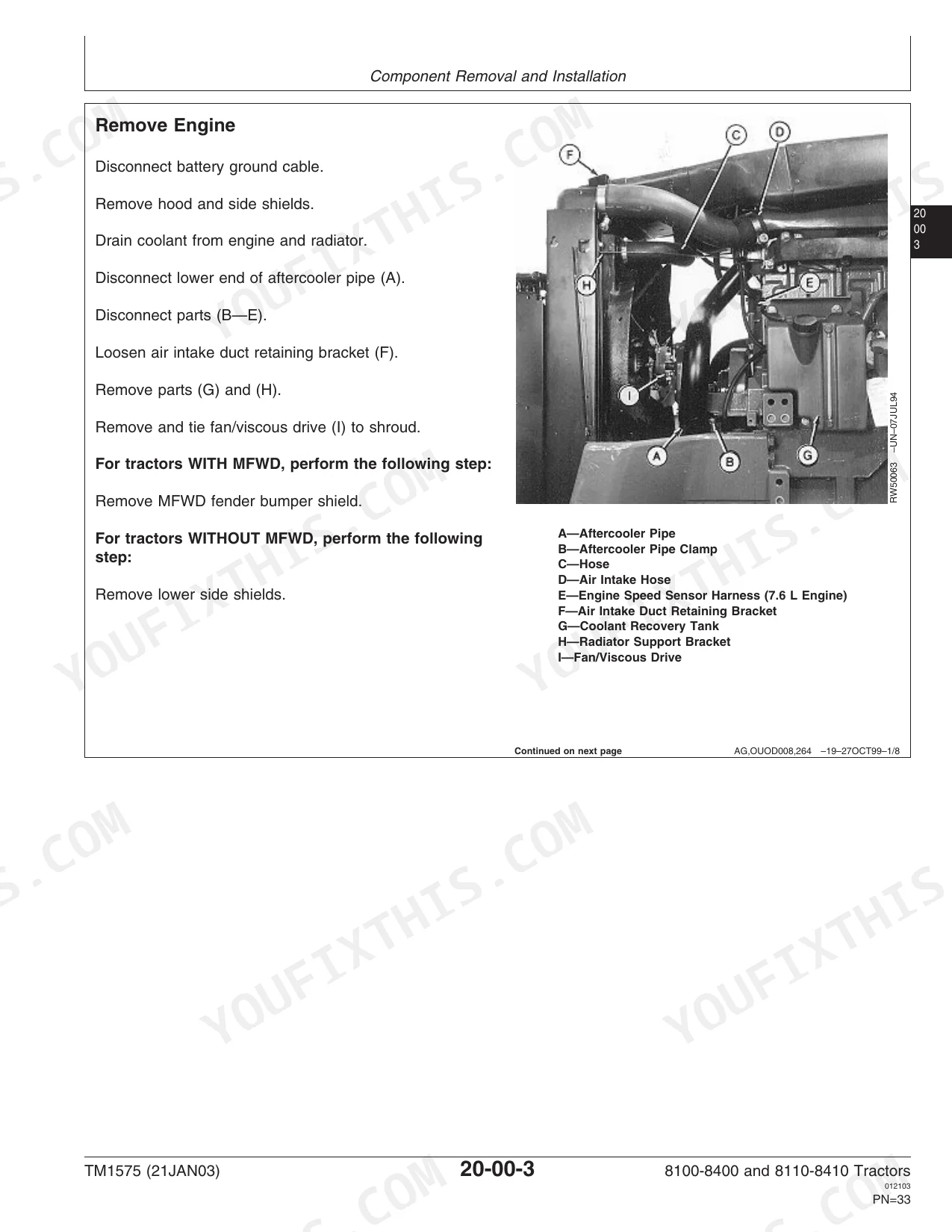
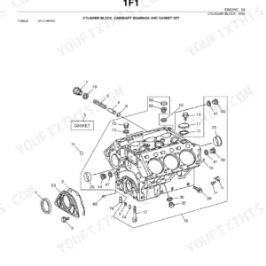
| Engine | - | Group 00 Component Removal and Installation, Group 05 Engine Repair, Essential or Recommended Tools (Lift Sling, Flywheel Rotation Tool, Torsional Damper Wrench), Specifications |
| Fuel and Cooling Systems | - | Diesel Fuel System, Air Intake System, Engine Cooling System, Radiator/Aftercooler, Air Conditioning Condenser and Coolers |
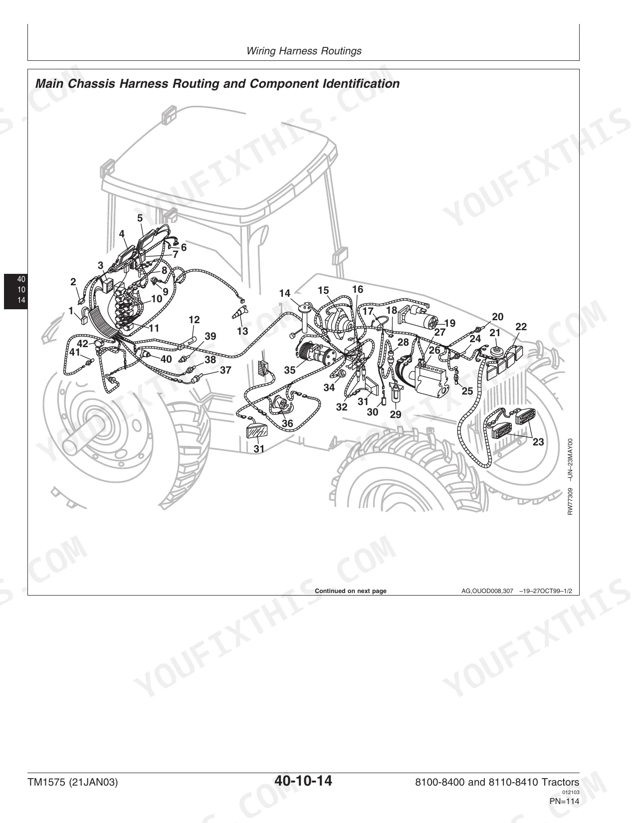
| Electrical - Harnesses & Connectors | - | Connectors, Wiring Harness Routings, Charging Circuit, Starting Circuit |
| Electrical - Solenoids & Sensors | - | Solenoids and Switches, Monitoring Systems and Sensors, Armrest Control, Implement and Accessory Connectors, Convenience and Accessory Components |
| Power Shift Transmission | - | Component Removal and Installation, Miscellaneous Repair, 8000 Series Transmission, 8000 Ten Series Transmission |
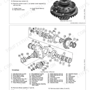
| Drive Systems - Differential & Final Drives | - | Component Removal and Installation, Rear Differential and Input Quill, Final Drives |
| Drive Systems - PTO & MFWD | - | Rear PTO, Hydraulic Pump Drive, MFWD Clutch, MFWD Axle Version 'a', MFWD Axle Version 'b', Drivelines |
| Steering and Brakes | - | Steering Column, Steering Control Assembly, Steering Cylinders, Brake Valve, Brake Components, Trailer Brakes |
| Hydraulics | - | Component Removal and Installation, Hydraulic System Repair and Cleanup, Tandem Hydraulic Pump, Secondary Hydraulic Pump, Hitch Valve, Hitch, Row Guidance |
| Miscellaneous & Operator Station | - | Front Axle (2-Wheel Drive), Wagon and Pick-Up Hitch, Cab Removal and Installation, HVAC, Air Conditioning System, Air Suspension Seat, Cab Door and Windshield |
| Dealer Fabricated Tools | - | Group 05 Fabricated Tools, Fabricated Tools, DF1057, Axle Adjusting Tool, DFRW2, Needle Valve Test Hose Assembly, DFRW12, Wheel Hub and Ring Gear Clamp |
Quick Reference Specifications
| Specification | Value | Page |
|---|---|---|
| All Models | ||
| Front Wheel-to-Hub Cap Screws (2-Wheel Drive) | 310 N•m (228 lb-ft) | p. 955 |
| Front Wheel-to-Hub Cap Screws (MFWD Axle Version "A") | 610 N•m (450 lb-ft) | p. 597 |
| Fuse F1 (Central Control Unit (CCU), Powershift Control Unit (PCU)) | 30A | p. 129 |
| Solenoid Plate Cap Screw | 18 N•m (159 lb-in.) | p. 146 |
| Draft Sensing Adjustment Screw Lock Nut—Torque | 25 N•m (221 lb-in.) | p. 187 |
| Draft Sensing Sensor—Voltage Adjustment Range | 1.6—1.7 V | p. 187 |
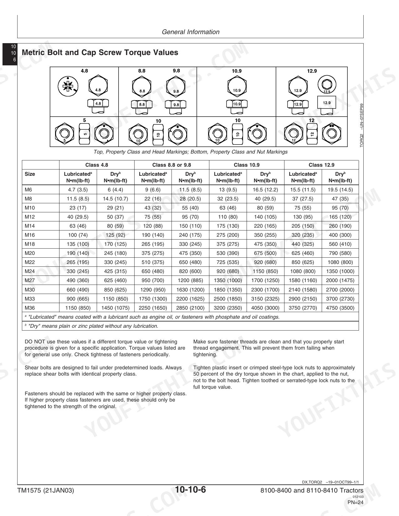
| Rated Speed | 2200 rpm | p. 21 |
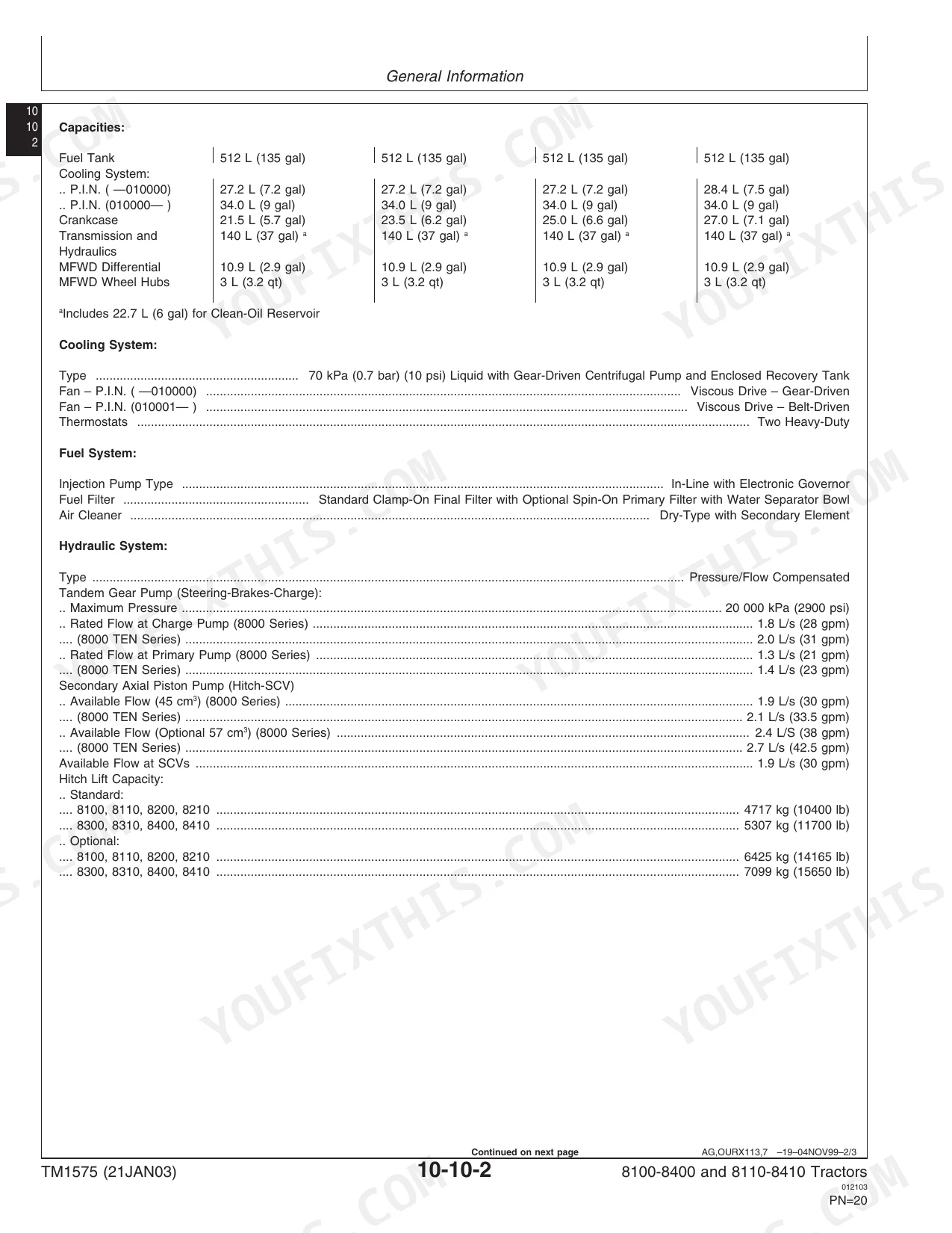
| Fuel Tank Capacity | 512 L (135 gal) | p. 22 |
| Steering Turns (Lock-to-Lock) | 3.7 | p. 23 |
| 8100, 8200, 8300, 8400 | ||
| Electro-Hydraulic Valve Retainer Clamp Cap Screws | 25 N•m (216 lb-in.) | p. 272 |
| 8100-8110 | ||
| PTO (8000 Series) Power | 119 kW (160 hp) | p. 21 |
| Crankcase Capacity (PIN -010000) | 21.5 L (5.7 gal) | p. 22 |
John Deere 8100–8410 Common Problems This Manual Covers
Under heavy load the 8200 throws a PCU 70 code and the transmission faults to neutral without warning
Inspect the armrest control wiring harness for damaged connectors. Check the Powershift Control Unit power circuit on page 129 and confirm the 30A fuse F1 is intact. Clean the ground connections, then tighten the solenoid plate cap screws to 18 N•m (159 lb-in.) as specified on page 146.
Manual Section: Electrical - Harnesses & Connectors p. 129PCU code 14 logs excessive clutch slip time and the tractor loses drive without warning
Remove and inspect the MFWD clutch assembly for worn friction plates. Measure the MFWD clutch disk thickness as shown on page 272. Replace the disks if they fall below the new specification of 2.9 mm (0.114 in.). Clean the shift valve manifold before reassembly.
Manual Section: Drive Systems - PTO & MFWD p. 272After transmission repairs on the 8410, a PCU 8 code stays active and shifting remains abnormal under load
Test the draft sensing sensor voltage and adjust the mechanical linkage. Torque the draft sensing adjustment screw lock nut to 25 N•m (221 lb-in.) following the procedure on page 187. Verify the radar unit to mounting bracket cap screws are at 28 N•m (20 lb-ft) on page 185.
Manual Section: Electrical - Solenoids & Sensors p. 187Engine turns over slowly in cold weather and the starting motor groans during engagement
Check the starting circuit voltage drop across the battery cables. Measure the starting motor current draw; it should pull 450 Amps at 11.1 volts as outlined on page 137. Inspect the damper to flywheel cap screws and confirm they are torqued to 70 N•m (52 lb-ft) on page 49.
Manual Section: Electrical - Harnesses & Connectors p. 137Frequently Asked Questions
What are the torque specs for John Deere 8100 front wheel hub bolts?
On 2-wheel-drive 8100 tractors, the front wheel hub cap screws torque to 310 N•m (228 lb-ft). MFWD models instead use the carrier assembly-to-wheel hub cap screws, set at 126 N•m (92 lb-ft). p. 960
What does a PCU 70 code mean on a John Deere 8200?
A PCU 70 code that faults the transmission to neutral points to the armrest control wiring. Inspect the harness for damaged connectors, check the Powershift Control Unit power circuit and 30A fuse F1 on page 129, clean the grounds, then torque the solenoid plate cap screws to 18 N•m (159 lb-in.) per page 146. p. 129
How do I fix a PCU 14 clutch-slip code on a John Deere 8000-series tractor?
PCU code 14 logs excessive clutch slip and loss of drive. Remove and inspect the MFWD clutch for worn friction plates, measure disk thickness on page 272, and replace the disks if they fall below 2.9 mm (0.114 in.). Clean the shift valve manifold before reassembly. p. 272
Why does a PCU 8 code persist after transmission repair on the 8410?
If a PCU 8 code stays active after transmission work on the 8410, test the draft sensing sensor voltage and adjust the mechanical linkage. Torque the draft sensing adjustment screw lock nut to 25 N•m (221 lb-in.) per page 187, and verify the radar mounting cap screws at 28 N•m (20 lb-ft) on page 185. p. 187
What do I get after purchasing this John Deere 8100 & variants manual?
Expect a 1124-page searchable PDF, ready to download right after checkout. It works on any device, so pull it up on your phone while you're under the hood. No shipping, no waiting.
Can I print specific sections of this John Deere 8100 & variants Repair Manual?
None at all. The PDF is DRM-free, so print whatever sections you want to carry out to the shop. Standard letter or A4 paper works fine.


Reviews
There are no reviews yet.