
Part of the John Deere Repair Manuals.
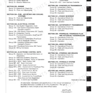
Chasing electrical gremlins across your John Deere 8110, 8210, 8310, or 8410 Tractor just got easier with this 466-page factory John Deere 8110 Diagnostic Manual PDF (OEM #TM1796). Inside, you get a massive breakdown of CCU, PCU, and SCU code diagnostics, plus complete sensor testing procedures and calibration steps. Wiring diagrams and hydraulic schematics are referenced by document number (e.g., 245-ACU-300, 270-25-003) for further lookup as external documents. Verify your engine oil pressure gauge sensor voltage reads 4.5V at low pressure and 0.5V at high pressure, then confirm the fuel level sensor hits 4.8V when full. Stop blindly swapping sensors and expensive modules. Download this bookmarked file right to your tablet, search for your specific fault code, and get the machine back to work.
What's Inside This John Deere 8110, 8210, 8310, 8410 Manual
| System | Pages | Key Topics |
|---|---|---|
| Introduction | 2-4 | Foreword |
| Safety | 5-18 | General, Group 05, Recognize Safety Information, Prevent Machine Runaway, Handle Fluids Safely, Avoid Fires, Prevent Battery Explosions |
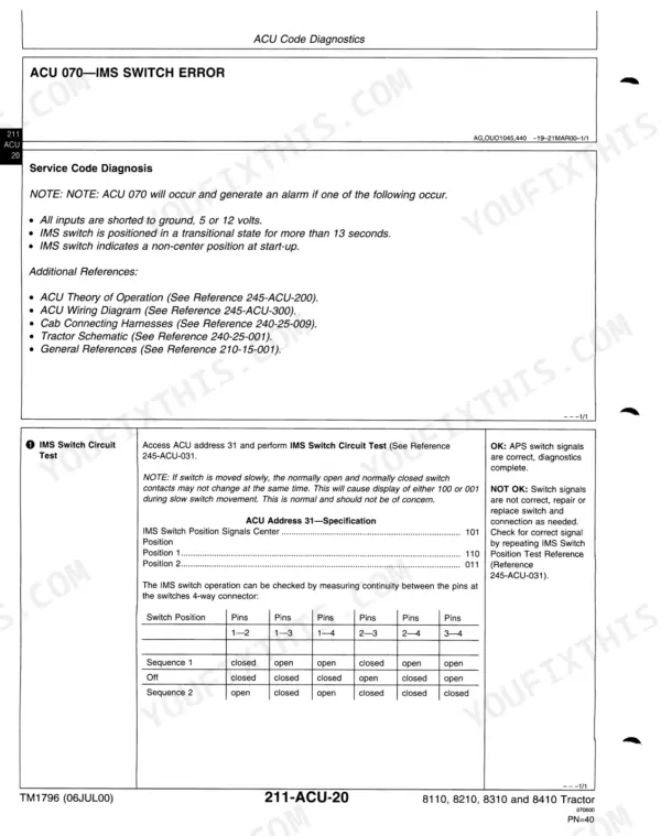
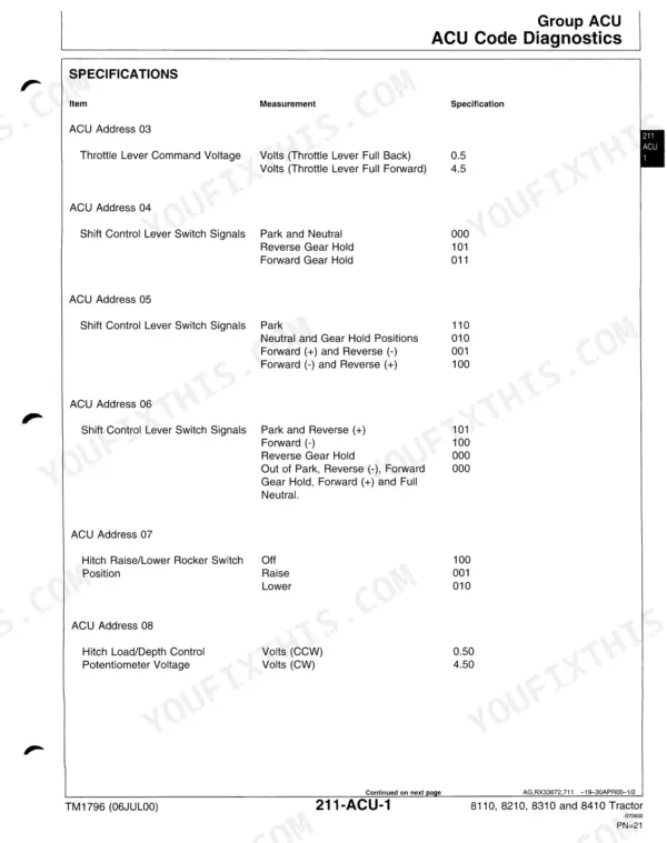
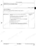
| Acu Code Diagnostics | 19-62 | Group Acu, Acu 120, SCV No 2 Control Switch Voltage, Acu 121, SCV No 2 Control Switch Status, Acu 130, SCV No 3 Control Switch Voltage |
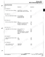
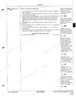
| Ccu Code Diagnostics | 63-158 | Specifications, Ccu 001, Fuel Level Sensor Circuit (Service Code Diagnosis), Ccu 005, Engine Oil Pressure Sensor Circuit (Service Code Diagnosis), Ccu 007 |
| Hcu Code Diagnostics | 159-184 | Specifications, Hcu 022, Battery Voltage Out of Range (Service Code Diagnosis, Voltage Check), Hcu 027, Calibration Not Successful (Service Code Diagnosis, Check for Related Codes) |
| Icu Code Diagnostics | 185-192 | Specifications, Icu 094, Vehicle Monitor Touch Switch Stuck (Service Code Diagnosis, Recall Codes), Icu 095, Not Receiving Ccd Data (Service Code Diagnosis, Ccd Network Diagnosis) |
| Pcu Code Diagnostics | 193-276 | Specifications, Pcu 005, Fuel Flow Signal From ECU Missing (Service Code Diagnosis, Ccu 056 Check, ECU/ Ccu Check), Pcu 006 |
| Scu Code Diagnostics | 277-302 | Specifications, Scu 022, Battery Voltage Out of Range (Service Code Diagnosis, Voltage Check), Scu 027, Calibration Not Successful (Service Code Diagnosis, Check for Related Codes) |
| SCo Code Diagnostics | 303-320 | Specifications, SCo 022, Battery Voltage Out of Range (Service Code Diagnosis, Voltage Check), SCo 027, Calibration Not Successful (Service Code Diagnosis, Check for Related Codes) |
| Sup Code Diagnostics | 321-327 | Sup 010, Communication From Scu Missing (Service Code Diagnosis, Ccd Network Diagnosis), Sup 011, Communication From SCo Missing (Service Code Diagnosis |
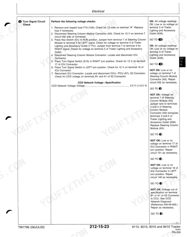
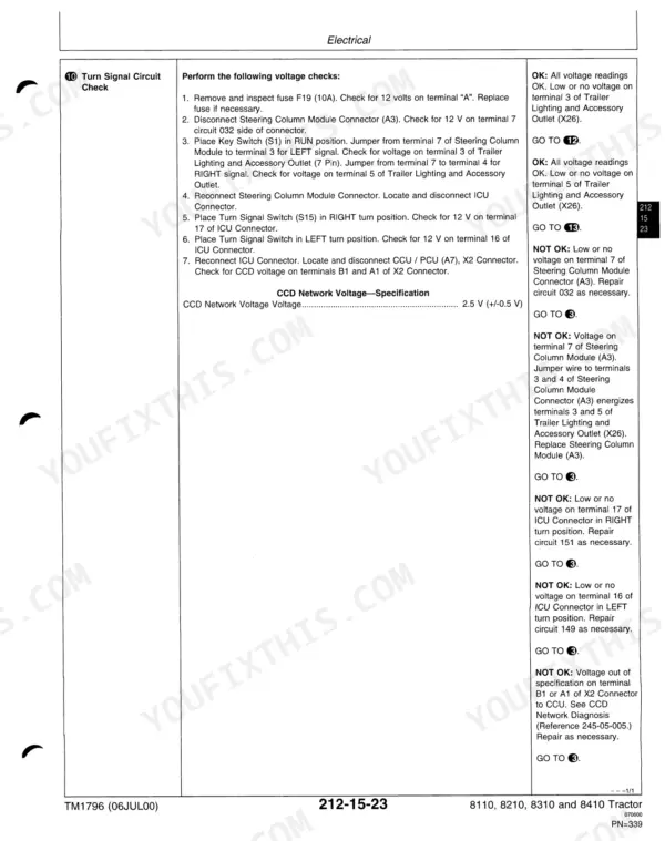
| Electrical | 328-365 | Electrical System Diagnosis, Charging & Lighting Circuits, Wiring Harness & Component Diagnosis, Observable Symptom Diagnosis |
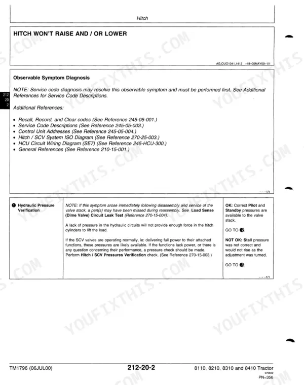
| Hitch | 366-375 | 3-Point Hitch Diagnosis, Position & Draft Control, Hitch Raise/Lower Symptoms, Observable Symptom Diagnosis |
| Heating, Ventilation and Air Conditioning (Standard) | 376-387 | Air Conditioning & Heater Diagnosis, Blower Circuit, ClimaTrak Controls, Observable Symptom Diagnosis |
| Heating, Ventilation and Air Conditioning - ClimaTrak™ (Atc) | 388-397 | Specifications, ClimaTrak™ Trouble Light Flashing (Observable Symptom Diagnosis, Access Light Codes), Diagnostic Trouble Lamp Does Not Light |
| Operator Station | 398-435 | Dust in Cab (Observable Symptom Diagnosis, Preliminary Operational Checks, Key Switch/ELX Relay Check, Pressurizer Blower Motor Run Test, Fuse F18 Check, Key Switch Check, Elx Relay Check, Circulation Blower Motor Check, Blower Motor Circuit Relay Check, Blower Motor Switch Check, Circulator Blower Harness Check, Pressurizer Blower Motor Check, Pressurizer Blower Motor Relay Check) |
| Power Take-Off | 436-443 | PTO Engagement Diagnosis, Rear PTO, PTO Clutch, Observable Symptom Diagnosis |
| Selective Control Valve | 444-453 | Specifications, Hose Ejects From SCV Coupler (Observable Symptom Diagnosis, Check for Trapped Pressure, Inspect Drain, Inspect Coupler) |
| Steering | 454-466 | Steering System Diagnosis, Power Steering Circuit, Hard/Erratic Steering, Observable Symptom Diagnosis |
Documents This Manual Refers To
The manufacturer cites these publications by number. We carry them:
Quick Reference Specifications
| Specification | Value | Page |
|---|---|---|
| Engine Oil Pressure Gauge Sensor Voltage (high pressure) | 0.5 | p. 63 |
| Engine Oil Pressure Gauge Sensor Voltage (low pressure) | 4.5 | p. 63 |
| Fuel Level Sensor Voltage (empty) | 0.0 | p. 64 |
| Fuel Level Sensor Voltage (full) | 4.8 | p. 59 |
| Engine Coolant Temperature Sensor Voltage (hot) | 0.5 | p. 63 |
| Engine Coolant Temperature Sensor Voltage (cold) | 4.5 | p. 63 |
| Fuse F14 Status Fuse F14 Good Installed | XX1 | p. 63 |
| Fuse F14 Status Fuse F14 Blown\ Removed | XX0 | p. 63 |
| Engine Oil Pressure Gauge Minimum No Load (Idle) Pressure | 100 kPa (1.0 bar) (15 psi) | p. 65 |
| Engine Oil Pressure Gauge Maximum Full Load (Rated Speed) Pressure | 450 kPa (4.5 bar) (65 psi) | p. 65 |
| Alternator Output Voltage-Specification Regulated Voltage | 13.2-14.2 volts | p. 103 |
| Transmission-Hydraulic Filter change | 750 hours | p. 120 |
John Deere 8110, 8210, 8310, 8410 Common Problems This Manual Covers
John Deere 8210 CCU 20/21 fault code triggers engine oil pressure low STOP ENGINE warning unexpectedly with correct oil level
Check the oil pressure sensor circuit in the CCU Code Diagnostics section starting page 63. Measure sensor output voltage: it should read 0.5V at high pressure and climb to 4.5V as pressure drops. Confirm actual pressure against spec on page 65: 100 kPa (15 psi) minimum at idle, 450 kPa (65 psi) at rated speed. Replace the sensor if voltage stays fixed regardless of measured pressure.
Manual Section: Ccu Code Diagnostics p. 65CCU 10 fault code shows coolant temperature high warning during heavy load despite visible coolant in the tank
Test the coolant temperature sensor circuit per the specifications on page 63 before condemning the radiator. With the engine hot, sensor voltage should read near 0.5V; a cold engine reads closer to 4.5V. If the reading stays high on a hot engine, suspect an open circuit or failed sensor rather than actual overheating. Verify connector pins are dry and free of corrosion before replacing the sensor.
Manual Section: Ccu Code Diagnostics p. 63CCU 1 fault code reports fuel level input open circuit or shorted above 12 volts, gauge shows no reading
Check the fuel level sensor circuit against the voltage specs on page 59: a full tank should read 4.8V, dropping toward 0.0V empty per the spec on page 64. An open circuit reads pegged high or absent; a short to voltage reads above 12V regardless of tank level. Inspect the connector and harness for chafing between the sender and CCU before replacing the sensor.
Manual Section: Ccu Code Diagnostics p. 59CCU 47 fault code calls for a voltage regulator replacement but the charging system still reads normal at idle
Verify alternator output on page 103 before swapping the regulator: regulated voltage should hold between 13.2 and 14.2 volts at operating RPM. Also confirm output capacity meets the 140 amp minimum at 13.2 volts spec on page 67. If voltage drifts outside range only under load, the regulator is the likely fault; if steady, check wiring and ground connections first.
Manual Section: Ccu Code Diagnostics p. 103CCU 49 fault code flags a transmission-hydraulic oil filter or fluid issue even after fuse F14 checks out good
Confirm fuse F14 status against page 122 first; a good fuse reads continuity with no visible break in the element. If the fuse is fine, check the transmission-hydraulic filter change interval on page 120: replace at 750 hours or sooner if the code persists. Drain and inspect fluid condition, then top off to the correct level before clearing the code and retesting.
Manual Section: Ccu Code Diagnostics p. 120CCU 7 fault code reports ECU does not match tractor model after an ECU replacement or software update
Pull up the CCU Code Diagnostics section beginning page 63 and confirm the installed ECU part number and calibration match the tractor's build configuration. Recheck that the software flash completed fully with no interrupted download; a partial update commonly leaves a mismatch flag active. If the mismatch persists after a clean reflash, the ECU requires dealer-level reprogramming to match the chassis serial number.
Manual Section: Ccu Code Diagnostics p. 63Frequently Asked Questions
How to reset John Deere 8110/8210/8310/8410 engine error codes?
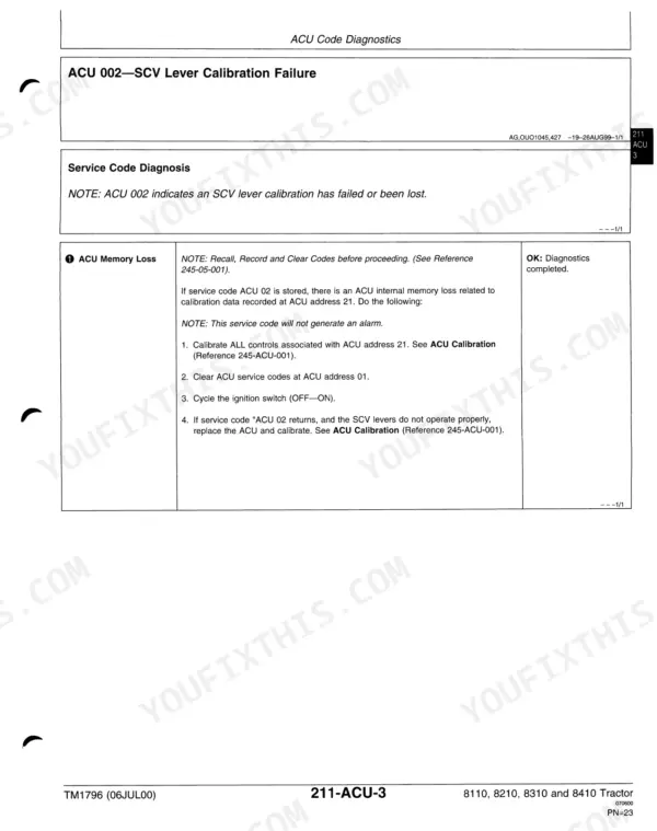
To reset service codes, which include engine error codes, first recall, record, and clear all codes. Then, cycle the ignition switch OFF and ON. For example, for ACU 002, clear ACU service codes at ACU address 01. p. 33
What do John Deere 8110 error codes mean and how to clear them?
Error codes, referred to as service codes, indicate specific system failures. Each code has a dedicated "Service Code Diagnosis" section explaining its meaning and providing troubleshooting steps. To clear them, you typically perform a "Recall, Record and Clear Codes" procedure (Reference 245-05-001) and then cycle the ignition. For example, ACU 002 indicates an SCV lever calibration has failed or been lost. p. 33
How to reset transmission adaptive learning on John Deere 8110?
Resetting transmission adaptive learning is typically done through a calibration procedure. For instance, if the PCU 027 code (Transmission Not Calibrated) is present, you should perform a PCU Calibration (Reference 245-PCU-001). p. 220
How to reset John Deere 8310 implement management system?
While there isn't a direct "reset" procedure for the entire Implement Management System (IMS), issues related to the Hitch Control Unit (HCU), which is part of IMS, can be addressed by performing an HCU Calibration (Reference 245-HCU-001). This calibration helps reset learned parameters for hitch control. p. 164
What do I get after purchasing this John Deere 8110 & variants manual?
This is a 466-page searchable PDF ready for immediate download. Works on any device, so pull it up on your phone while you're under the hood. No shipping, no waiting.
Are there any print restrictions on this John Deere 8110 & variants manual?
Yes, print as many copies as you want, and there are no restrictions. Many mechanics print the section they need and bring it to the shop floor.
Are there wiring harness diagrams in this John Deere 8110 & variants manual?
Wiring diagrams are referenced in this manual (e.g., 245-ACU-300, 240-25-001) but are external documents not included in this PDF. The manual itself focuses on ACU/CCU/PCU code diagnostics and sensor testing procedures for the John Deere 8110 & variants.








Reviews
There are no reviews yet.