Part of the John Deere Repair Manuals.
This is the factory technical manual John Deere dealers used on the 5200, 5300, 5400 and 5500 tractors built from 1992 to 1998. It covers both jobs a shop actually does: full component repair (engine, transmission, clutch, differential, final drives, MFWD, hydraulics, steering, brakes, 3-point hitch, cab and air conditioning) and the operation, tests and adjustments sections you need before you tear anything apart - injection pump timing, fuel bleed procedure, hydraulic pressure tests, wiring schematics and operational checkouts. Real numbers, not guesswork: 33 L/min minimum pump flow on the 5200/5300/5400, 60 L/min on the 5500, main relief at 190-197 bar, thermostat opening at 82 C. If you keep one of these tractors working, this is the book.
Other edition of this manual
What's Inside This John Deere 5200, 5300, 5400, 5500 Manual
| System | Pages | Key Topics |
|---|---|---|
| General Information | 9-74 | Safety, General Specifications, Fuel and Lubricants, Serial Number Locations, Features and Accessories |
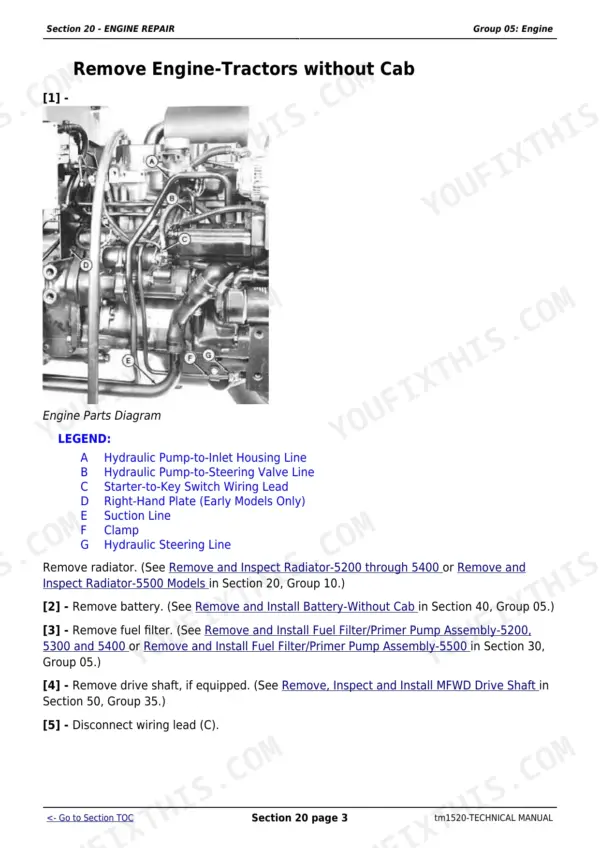
| Engine Repair | 75-126 | Engine, Cooling System |
| Fuel and Air Repair | 127-164 | Fuel System, Air Intake System, Speed Control Linkage |
| Electrical Repair | 165-243 | Battery, Starter and Alternator, Electrical System Components, Wiring Harness |
| Power Train Repair | 244-648 | Clutch Housing, Transmission, Rear PTO Drive Shaft, Differential, Final Drives, MFWD, Creeper Assembly |
| Steering and Brake Repair | 649-704 | Steering Valve Disassembly and Assembly, Cylinder, Tie Rods, Hoses and Fittings; Valve Service, Disc and Back Plate, Piston and Cross Beam, Hydraulic Lines |
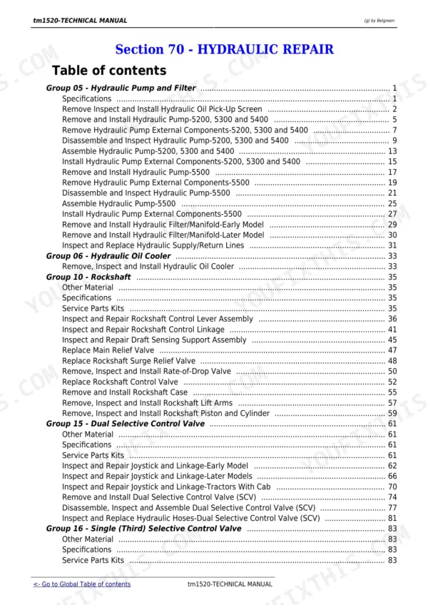
| Hydraulic Repair | 705-808 | Hydraulic Pump and Filter, Hydraulic Oil Cooler, Rockshaft, Selective Control Valves, Mid Mount Coupler, Power Beyond |
| Miscellaneous Repair | 809-833 | Front Axle-2WD, Wheels, 3-Point Hitch |
| Operator Station Repair | 834-962 | Seat and Support, Roll-Gard, Cab Components, Air Conditioning System, Heating System |
| Operational Checkout Procedures | 963-996 | Starting Checkout, Transmission Neutral Start Check, PTO Neutral Start Check |
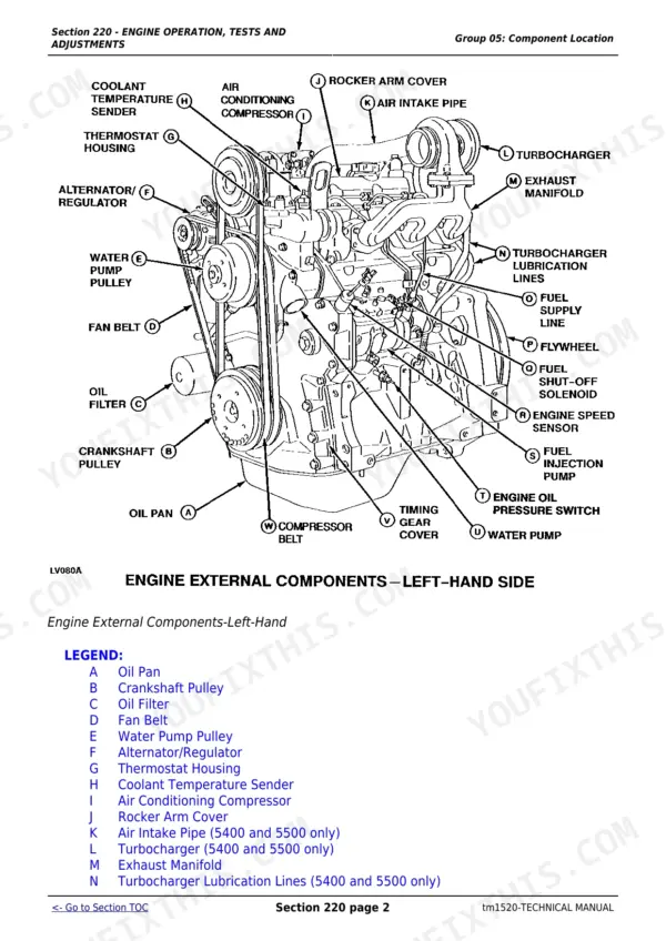
| Engine Operation Tests and Adjustments | 997-1058 | Engine Diagnosis, Injection Pump Timing, Cooling System Theory, Fuel Bleed Procedure |
| Fuel/Air Operation Tests and Adjustments | 1059-1084 | Filter and Primer Pump Locations, Injection Pump and Nozzle Operation, Intake System Operation, Turbocharger Diagnosis |
| Electrical System Operation Tests and Adjustments | 1085-1399 | Charging System Theory, Wiring Schematics, Starting System Tests |
| Power Train Operation Tests and Adjustments | 1400-1576 | Transmission Tests, Clutch Tests, PTO Tests |
| Steering and Brake Operation Tests and Adjustments | 1577-1632 | Steering Tests, Brake Tests |
| Hydraulic System Operation Tests and Adjustments | 1633-1751 | Hydraulic System Tests, Hydraulic Schematics, Rockshaft Tests |
| Operator Station | 1752-1811 | Component Locations, Theory of Operation, Diagnosis and Tests |
| Dealer Fabricated Tools | 1812-1818 | Dealer Fabricated Special Tools |
Quick Reference Specifications
| Specification | Value | Page |
|---|---|---|
| 5200/5300 Engine Displacement | 2.9 L (179 cu in.) | p. 29 |
| 5400 Engine Displacement | 2.9 L (179 cu in.) | p. 34 |
| 5500 Engine Displacement | 3.9 L (239 cu in.) | p. 34 |
| 5200/5300 Rated Engine Speed | 2400 rpm | p. 29 |
| 5400/5500 Rated Engine Speed | 2400 rpm | p. 34 |
| 5200/5300 Hydraulic System Capacity | 38 L (10 U.S. gal) | p. 30 |
| 5400/5500 Hydraulic System Capacity | 38 L (10 U.S. gal) | p. 35 |
| 5200/5300/5400 Hydraulic Pump Flow (at pump, 2000 rpm) | 33 L/min (8.8 gpm) minimum | p. 1713 |
| 5500 Hydraulic Pump Flow (at pump, 2000 rpm) | 60 L/min (16 gpm) minimum | p. 1713 |
| Hydraulic Main Relief Pressure | 18995-19685 kPa (190-197 bar) (2755-2855 psi) | p. 1713 |
| Alternator Voltage Regulation | 14.2-14.8 V at 25 C (77 F), 5000 rpm, 10A | p. 1115 |
| Injection Pump Mounting Nut Torque | 25 N.m (216 lb-in.) | p. 1037 |
| Thermostat Opening Temperature | 82 C (180 F) | p. 1008 |
| Radiator Pressure Cap Relief | 48 kPa (0.48 bar) (7 psi) | p. 1008 |
John Deere 5200, 5300, 5400, 5500 Common Problems This Manual Covers
Engine overheating
The pressurized cooling system's thermostat opens at 82 C (180 F) to send full flow through the radiator, and the pressure cap releases into the coolant recovery tank at 48 kPa (0.48 bar / 7 psi). Check coolant level, radiator core cleanliness, fan belt tension, and thermostat operation against those two values before condemning the water pump.
Manual Section: Engine Operation Tests and Adjustments - Cooling System p. 1008Engine hard starting or will not start
Run the Transmission and PTO Neutral Start Checks first (the starter should not crank with the shift lever engaged or PTO on), then follow the Engine Turns Over but Will Not Start or Starts Hard diagnostic chart, which walks through fuel supply, air in the fuel system, and the injection pump bleed procedure before the injection pump itself is suspected.
Manual Section: Operational Checkout Procedures / Engine Operation Tests and Adjustments p. 979Charging system will not charge or battery goes dead
Confirm battery, alternator, and regulator wiring against the charging-circuit theory, then verify alternator output. The integrated regulator should hold 14.2-14.8 volts at 25 C (77 F), 5000 rpm and 10 amps - a reading outside that band with good connections and belt tension points to the alternator or regulator itself.
Manual Section: Electrical System Operation Tests and Adjustments - Charging System p. 1115Weak hydraulics - slow or soft rockshaft, will not hold a load
Run the 4-step hydraulic test: pump flow at 2000 rpm should read at least 33 L/min (8.8 gpm) on 5200/5300/5400 or 60 L/min (16 gpm) on 5500, main relief pressure at slow idle should read 18995-19685 kPa (190-197 bar / 2755-2855 psi), then leak-test the rockshaft with and without the power-beyond pipe plug installed. A high or low relief reading means adjust the valve; a rockshaft that will not hold load points to the cylinder seals, piston, or surge relief valve.
Manual Section: Hydraulic System Operation Tests and Adjustments p. 1713Frequently Asked Questions
How do you bleed air from the fuel system after servicing the filter or fuel lines?
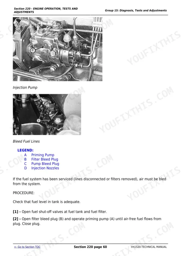
Open the fuel shut-off valves at the tank and filter, then open the filter bleed plug and operate the priming pump until air-free fuel flows out, and close the plug. Then remove the injection pump bleed plug and operate the priming pump again until air-free fuel appears there too, and reinstall the plug. Do not crank the starter to bleed the system - it can damage the injection pump. p. 1053
Does the manual include wiring diagrams for troubleshooting electrical faults?
Yes. Section 240 Group 20 (Wiring Schematics) prints full circuit diagrams with connector and component legends, including model/option-specific sheets such as the Electrical Schematic (Optional Equipment) for early 5200-5400 models without a cab. p. 1376
Does the manual include hydraulic system schematics?
Yes. Section 270 Group 20 (Hydraulic Schematics) prints the full hydraulic circuit, including the Hydraulic System Schematic - Without Selective Control Valves, with pump, valve, and rockshaft callouts. p. 1743
What is the charging system voltage regulator setting?
The regulator (a non-adjustable integrated-circuit type inside the alternator) is specified at 14.2-14.8 volts at 25 C (77 F), 5000 rpm and 10 amps. p. 1115
Which engines and models exactly does this manual apply to?
5200 (engine 3029DLV01, 34 kW/45.6 hp), 5300 (3029DLV02, 37 kW/50 hp), 5400 and 5500 - the 5200/5300/5400 share the 2.9 L (179 cu in.) three-cylinder, the 5500 uses the 3.9 L (239 cu in.) engine, all rated at 2400 rpm. p. 29