
Part of the John Deere Repair Manuals.
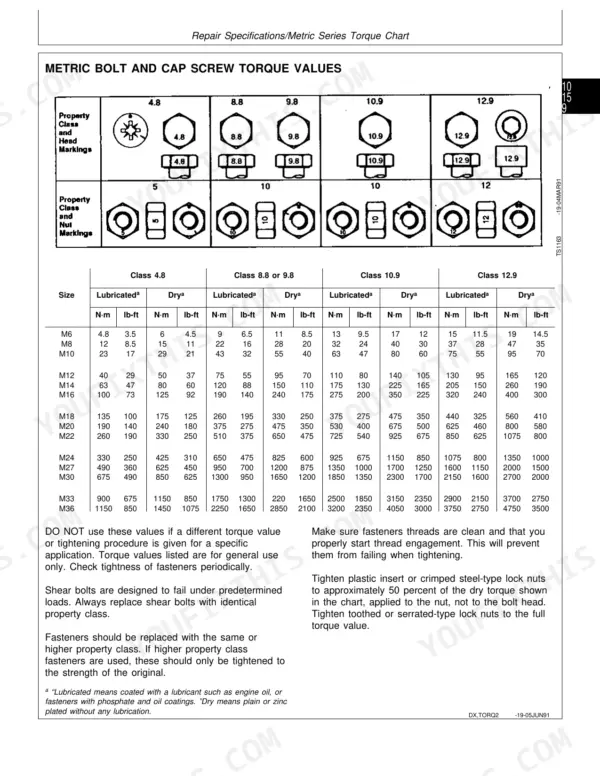
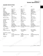
All 820 pages of this John Deere Technical Manual (OEM #TM1520) focus on one thing: getting your 5200, 5300, 5400, or 5500 tractor back to factory spec. If you're hunting for a John Deere 5400 technical manual pdf, this is the OEM source. Inside: full electrical wiring schematics, hydraulic schematics covering rockshaft, SCV circuits, and pump assemblies, a complete troubleshooting section across every major system, and a deep library of exploded views spanning engine, power train, differential, and final drives. When you pull the dual clutch, traction disc minimum thickness is 6.50 mm (0.260 in.) and the clutch-to-flywheel cap screws torque to 36 N·m (27 lb-ft). Hydraulic pump minimum flow checks at 42 Lpm (11 gpm). No more piecing specs together from scattered sources. Bookmarked and keyword-searchable; jump straight to the section you need.
Other edition of this manual
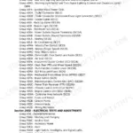
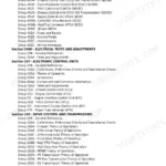
What's Inside This John Deere 5200, 5300, 5400, 5500 Manual
| System | Pages | Key Topics |
|---|---|---|
| General Information | Safety, General Specifications, Repair Specifications, Fuel and Lubricants, Serial Number Locations, Features and Accessories | |
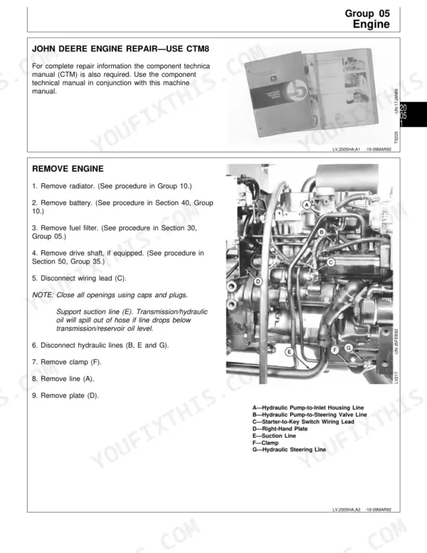
| Engine Repair | Engine Remove, Engine Install, Cooling System Remove and Inspect Radiator, Cooling System Install Radiator, Cooling System Replace Thermostat | |
| Fuel and Air Repair | Fuel System Injection Pump, Nozzle and Governor Repair, Fuel System Remove, Inspect and Install Fuel Tank, Fuel System Replace Fuel Filter, Air Intake System Remove | |
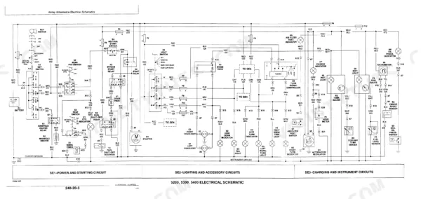
| Electrical Repair | Battery Remove and Install, Starter Remove and Install, Alternator/Regulator Replace, Key Switch Replace, Instrument Panel Replace, Wiring Harness Replace | |
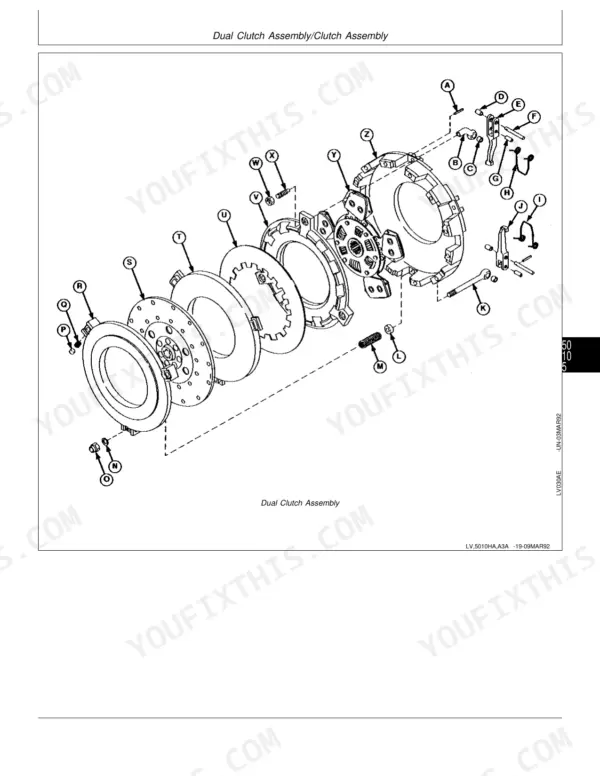
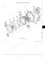
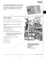
| Power Train Repair | Clutch Housing Separate Engine From Clutch Housing, Dual Clutch Assembly Remove and Install, Collar Shift Transmission Remove Transmission | |
| Steering and Brake Repair | Steering Column Remove and Install, Steering Valve Disassemble and Inspect, Steering Cylinder Remove and Install, Tie Rod Assembly Remove, Inspect and Install | |
| Hydraulic Repair | Hydraulic Pump Remove and Install, Hydraulic Pump Disassemble and Inspect, Rockshaft Control Lever Inspect and Repair, Rockshaft Case Remove and Install | |
| Miscellaneous Repair | Front Axle Remove and Install, Pivot Pin and Bushings Inspect and Replace, Spindle Assembly Remove and Install, Front Wheel Bearings Inspect and Replace | |
| Operator Station Repair | Seat Assembly, Roll-Gard Crossbar, Roll-Gard Posts, Roll-Gard Pivot Pins, Roll-Gard Locking Pins, Roll-Gard Stabilizers | |
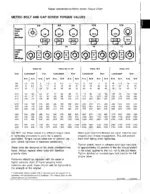
| Test and Adjustment Specifications/Operational Checkout Procedures | Engine Performance Test Specs, Hydraulic Pressure Specifications, PTO Output Load Tests, Fuel System Pressure Specs, Pre-Delivery Operational Checkout Sequence, System Torque Tolerances | |
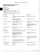
| Engine Operation, Tests and Adjustments | Engine Timing Checks, Cylinder Compression Tests, Valvetrain Adjustment, Oil Pressure Tests, Coolant Temperature Diagnostics, Engine No-Load Speed Verification | |
| Fuel/Air Operation, Tests and Adjustments | Fuel Injection Pump Tests, Nozzle Pressure Checks, Governor Operation Tests, Air Intake Restriction Tests, Fuel Filter Flow Tests, Cold-Start Diagnostics | |
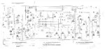
| Electrical System Operation, Tests and Adjustments | Component Location, Theory of Operation, Diagnosis, Tests and Adjustments, Wiring Schematics | |
| Power Train Operation, Tests and Adjustments | Clutch Engagement Pressure Tests, Transmission Shift Adjustment, PTO Slip Tests, Differential Lock Operation, Gear-Shift Fork Wear Checks, Clutch Pedal Free-Play Adjustment | |
| Steering and Brake Operation, Tests and Adjustments | Steering Valve Pressure Tests, Steering Cylinder Leak Checks, Brake Pedal Free-Play Adjustment, Brake Lining Wear Checks, Steering Angle Limit Tests | |
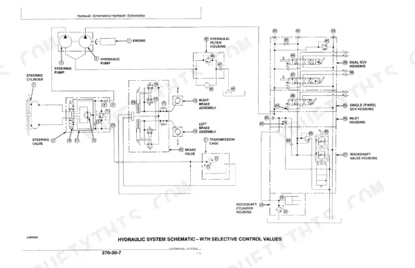
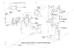
| Hydraulic System Operation, Tests and Adjustments | Component Location, Theory of Operation, Diagnosis, Hydraulic Tests Without SCV, Hydraulic Tests with SCV, Hydraulic Tests All, Adjustments, Hydraulic Schematics | |
| Dealer Fabricated Tools | Tool Drawings and Dimensions, Material Specifications, Fabrication Instructions, Recommended Tolerances, Tool Usage Procedures |
Quick Reference Specifications
| Specification | Value | Page |
|---|---|---|
| All Models | ||
| Clutch-to-Flywheel Cap Screw Torque | 36 N·m (27 lb-ft) | p. 25 |
| Traction Clutch Disc Minimum Thickness | 6.50 mm (0.260 in.) | p. 25 |
| PTO Clutch Disc Minimum Thickness | 5.50 mm (0.220 in.) | p. 25 |
| PTO Clutch Front Pressure Plate Minimum Thickness | 17.30 mm (0.680 in.) | p. 25 |
| Hydraulic Pump—Without SCV Pump Flow (Min) | 42 Lpm (11 gpm) | p. 327 |
| Hydraulic Pump—Without SCV Pump Pressure (Relief) | 18995—19685 kPa (190—196.8 bar) (2755—2855 psi) | p. 327 |
| Fuel Tank Capacity | 68 L (18 U.S. gal) | p. 23 |
| Engine-to-Clutch Housing Cap Screw Torque | 318 N·m (235 lb-ft) | p. 25 |
| Wheel Nut Torque | 300 N·m (220 lb-ft) | p. 26 |
| 5200 | ||
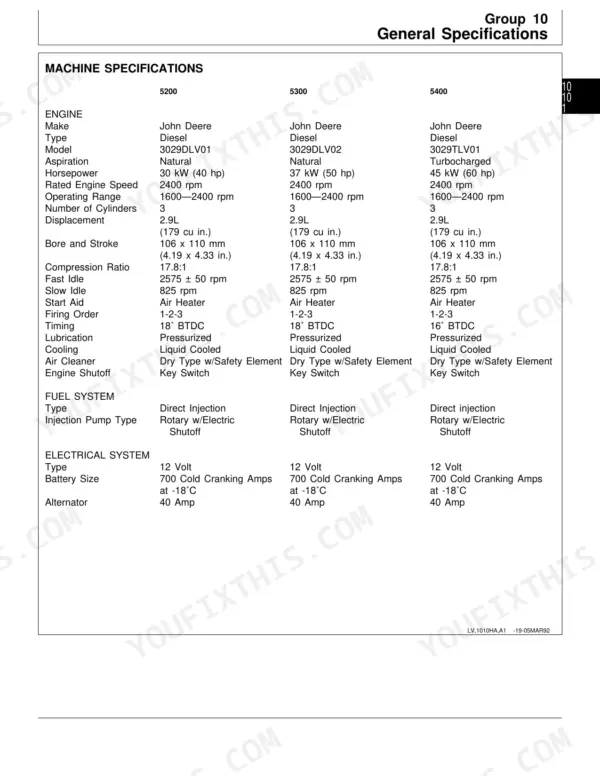
| Engine Horsepower, 5200 | 30 kW (40 hp) | p. 21 |
| 5300 | ||
| Engine Horsepower, 5300 | 37 kW (50 hp) | p. 21 |
| 5400 | ||
| Engine Horsepower, 5400 | 45 kW (60 hp) | p. 21 |
John Deere 5200, 5300, 5400, 5500 Common Problems This Manual Covers
Hydraulic lift raises slowly, won't hold position under load, or rockshaft won't move
Warm the system and check hydraulic oil level first. Inspect and clean the pickup screen inside the hydraulic sump, since screen clogging is the top cause of low flow. Test pump output at page 327 specs: minimum 42 Lpm (11 gpm) without SCV. If flow is low but pressure reads normal, suspect the pump itself.
Manual Section: Hydraulic System Diagnosis (General) p. 327Engine cranks but won't start, hard to start in cold weather, or stalls at low idle
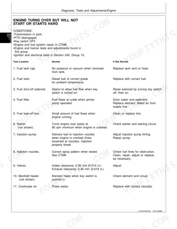
Check fuel level and bleed air from the fuel system before anything else. Run through the troubleshooting chart starting to isolate whether the fault is fuel, air, or electrical. Verify slow idle speed is within 775—875 rpm. Inspect the fuel filter and replace if more than one season old.
Manual Section: Engine Diagnosis: No Start, Rough Idle, Low Power, Noise, Smoke, Oil Pressure, Coolant TempCoolant temperature gauge climbs into the red, engine overheats, or coolant boils out of reservoir
Pressure-test the radiator cap; it should hold 48 kPa (7 psi) before the relief opens, per page 325 specs. Check for a stuck thermostat: normal operating temperature is 82°C (180°F). Inspect the radiator core for debris blocking airflow. Test for combustion gases in the coolant using a chemical block test kit.
Manual Section: Cooling System Tests p. 325Frequently Asked Questions
What are the replacement specifications for Clutch assembly?
For clutch assembly replacement, the Clutch-to-Flywheel Cap Screw Torque is 36 N·m (27 lb-ft). The minimum thickness for the Traction Clutch Disc is 6.50 mm (0.260 in.), and for the PTO Clutch Disc, it is 5.50 mm (0.220 in.). Additionally, the PTO Clutch Front Pressure Plate has a minimum thickness of 17.30 mm (0.680 in.), and the PTO Clutch Rear Pressure Plate is 18.80 mm (0.740 in.). p. 25
What are the replacement specifications for PTO cover mechanism or clutch?
For PTO clutch components, the minimum thickness for the PTO Clutch Disc is 5.50 mm (0.220 in.). The PTO Clutch Front Pressure Plate has a minimum thickness of 17.30 mm (0.680 in.), and the PTO Clutch Rear Pressure Plate has a minimum thickness of 18.80 mm (0.740 in.). p. 25
How do you fix john Deere 5200 clutch slips under heavy load, vibrates, or won't fully engage?
Check clutch pedal free play; the correct spec is 13—20 mm (0.500—0.750 in.) as shown on page 326. Adjust the linkage before assuming internal wear. If slip continues after adjustment, separate the engine from the clutch housing and measure traction clutch disc thickness. Discs worn below 6.50 mm (0.260 in.) must be replaced. p. 326
How do you fix PTO shaft won't spin or drops out of engagement under implement load?
Inspect the PTO engagement lever and linkage for binding or excessive slack. Remove the PTO cover and measure disc thickness; discs worn below 5.50 mm (0.220 in.) must be replaced. Torque the cover-to-differential case cap screws to 48 N·m (65 lb-ft) on reassembly, as specified on page 26. p. 26
How will I receive this John Deere 5200 Technical Manual?
You get a 820-page searchable PDF that downloads instantly after checkout. Open it on your laptop, tablet, or phone, and bring it right to the shop floor.
Can I print this manual?
Yes. Print the pages or sections you need for your own shop use. Any standard printer works.
Are hydraulic diagrams part of this John Deere 5200 Technical Manual?
Yes, this John Deere 5200, 5300, 5400, 5500 Technical Manual includes a hydraulic system diagram.