


Part of the John Deere Repair Manuals.
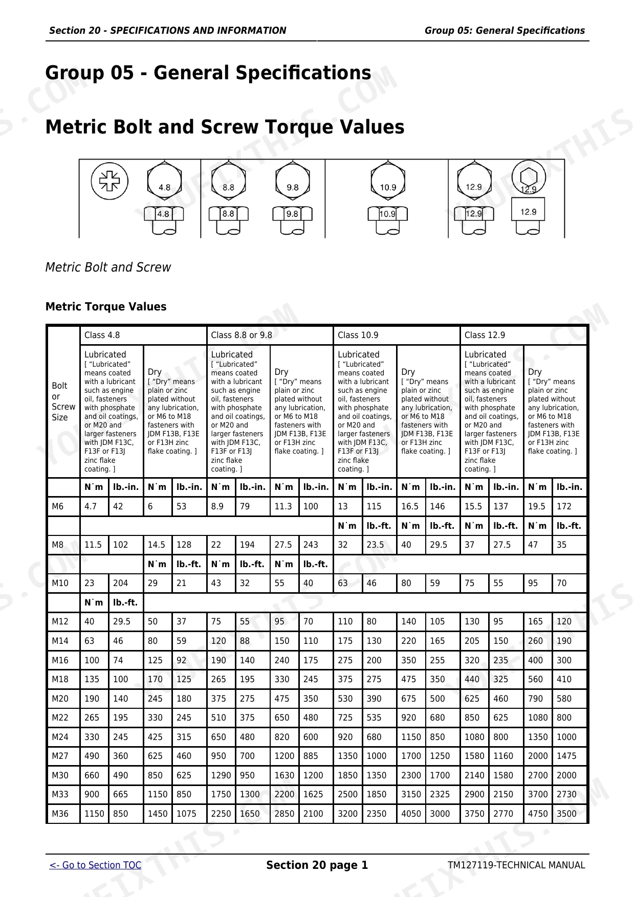
All 1,300 pages of this John Deere 2027R, 2032R Technical Manual (OEM #TM127119) cover one machine family: your Compact Utility Tractor, down to the last factory spec. Inside: full wiring schematics for both domestic and export electrical configurations, complete hydraulic routing diagrams with operation and diagnostics, and a hydrostatic power train section that runs from theory of operation through full teardown and rebuild. You also get metric and unified inch torque tables, O-ring fitting service procedures, fuel and lubricant specs (engine oil, coolant, transmission fluid), and troubleshooting sequences that trace faults by system. The hydraulic system relief valve is set to 16,692 ± 490 kPa (2421 ± 71 psi); confirm the forward directional control valve at 31,316 kPa (4542 psi) before you button anything back up. Your machine is down. Bookmarked by section and searchable by keyword, get the factory answer in seconds, not scroll sessions.
What's Inside This John Deere 2027R, 2032R Manual
| System | Pages | Key Topics |
|---|---|---|
| Safety | 7-30 | Recognize Safety Information, Understand Signal Words, Replace Safety Signs, Handle Fluids Safely-Avoid Fires, Prepare for Emergencies, Prevent Battery Explosions |
| Specifications and Information | 31-57 | Fuel and Lubricants (Diesel Fuel, Handling and Storing Diesel Fuel, Diesel Engine Oil, Diesel Engine Break-In Oil, Alternative and Synthetic Lubricants, Lubricant Storage, Mixing of Lubricants, Grease, Transmission and Hydraulic Oil, Heavy Duty Diesel Engine Coolant) |
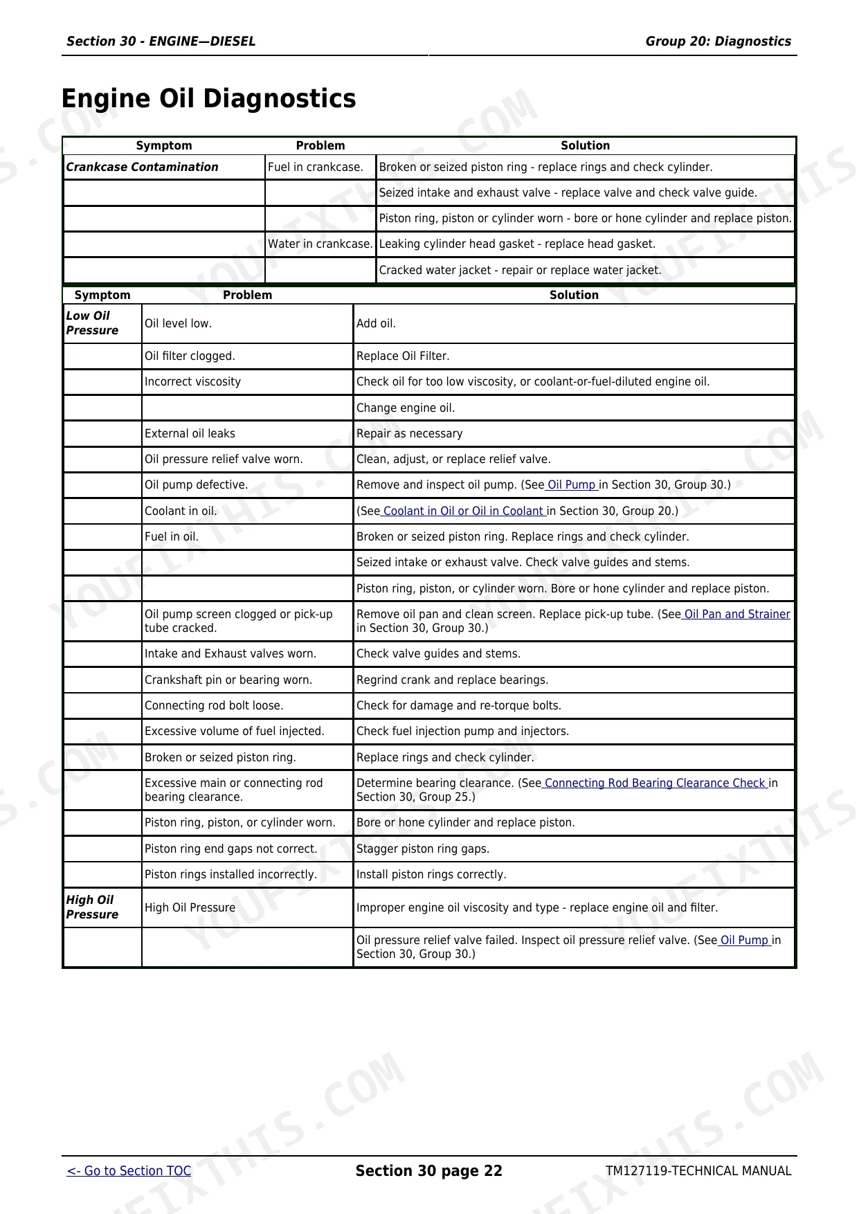
| Engine, Diesel | 58-327 | Specifications, Theory of Operation, Component Location, Diagnostics, Tests and Adjustments, Repair |
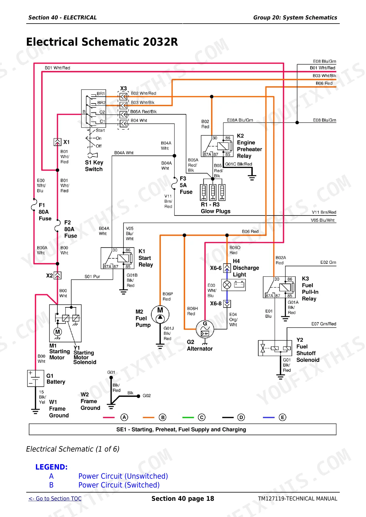
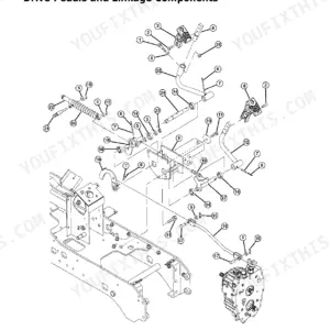
| Electrical | 328-589 | General Information, Specifications, Component Location, System Schematics, Diagnostics & Operation |
| Export Electrical | 590-758 | Specifications, Component Location, System Schematics, Diagnostics & Operation |
| Power Train, Hydrostatic | 759-1062 | Specifications, Component Location, Diagnostics, Theory of Operation, Tests and Adjustments, Repair |
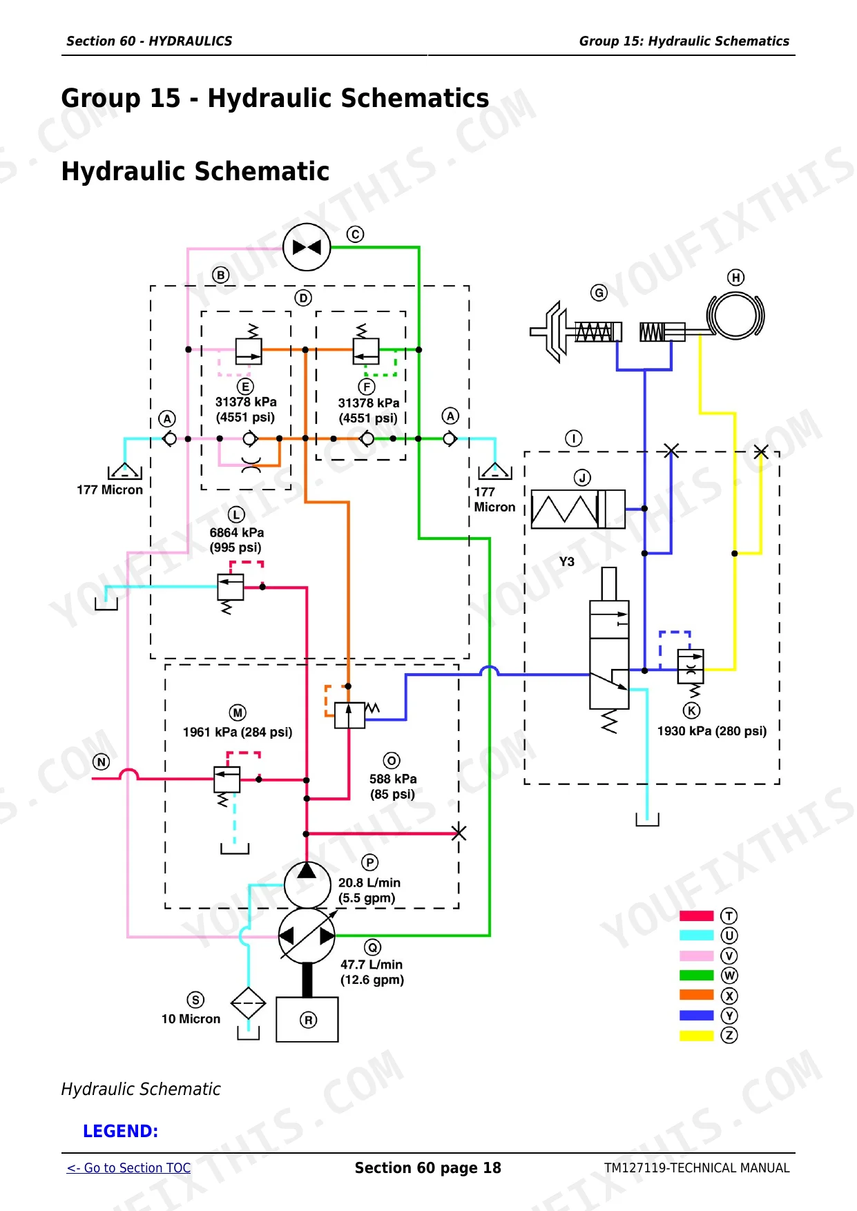
| Hydraulics | 1063-1192 | Specifications, Component Locations, Hydraulic Schematics, Operation and Diagnostics, Troubleshooting |
| Steering | 1193-1218 | Specifications, Component Location, Theory of Operation, Diagnostics, Tests and Adjustments, Repair |
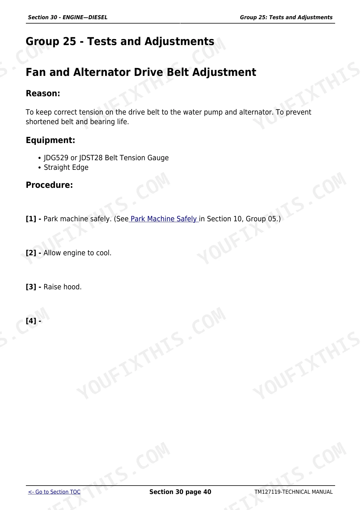
| Brakes | 1219-1261 | Wet Multiple Disk Brakes, Brake Pedals and Linkage, Park Brake Lever and Ratchet, Brake Rods and Turnbuckles, Park Brake Lock Link, Pedal Free Play Adjustment |
| Miscellaneous | 1262-1300 | Specifications, Repair |
Quick Reference Specifications
| Specification | Value | Page |
|---|---|---|
| All Models | ||
| System Relief Valve Pressure | 16 692 ± 490 kPa (2421 ± 71 psi) | p. 1064 |
| Forward Directional Control Valve Pressure | 31 316 ± 1 471 kPa (320 ± 15 kgf/cm²) (4542 ± 213 psi) | p. 1064 |
| Lift at Link Arms Capacity | 650 kg (1433 lb.) | p. 1065 |
| Lift Arm Angle Stroke (Working) | 75° | p. 1065 |
| Engine Oil Capacity | 2.8 L (3 qt.) | p. 58 |
| Cooling System Capacity | 3.9 L (4 qt.) | p. 58 |
| Crankshaft Main Bearing Bolts Torque | 93.2–98 N·m (69–72 lb.-ft.) | p. 66 |
| Battery Voltage | 12 VDC | p. 338 |
| Alternator Regulated Voltage | 14.2–14.8 VDC | p. 338 |
| Transmission Sump Holds Approximately | 14.6 L (3.9 gal.) | p. 759 |
| 2027R | ||
| Engine Torque (3TNV82A @ 2600 rpm) | 69.6 N·m (51.36 lb.-ft.) | p. 58 |
| 2032R | ||
| Engine Torque (3TNV88 @ 2500 rpm) | 86.7 N·m (63.98 lb.-ft.) | p. 58 |
John Deere 2027R, 2032R Common Problems This Manual Covers
Engine overheats or coolant level drops after service interval
Bleed cooling system air pockets immediately after any coolant work. Refill to the 3.9 L (4 qt.) system capacity, then loosen the bleed bolt at the highest point in the coolant circuit until coolant flows without bubbles, then torque it back snug. Run the engine to operating temperature, shut down, and recheck level. Air trapped in the lines is the primary cause of false-low coolant readings and recurring overheat on this platform.
Manual Section: Engine, Diesel p. 58Gear case reads correct on dipstick but runs dry or overheats after fill
After draining and refilling the gear case, wait a full 60 minutes before checking the dipstick. Fluid needs time to settle into all internal passages; checking immediately reads falsely high and causes underfilling. Top off only after the wait period, then recheck. Repeat the dipstick check after the first hour of operation at normal load, since trapped air pockets can displace fluid back through the breather.
Manual Section: Power Train, Hydrostatic p. 759Engine cranks but won't start or cranks slowly in cold conditions
Check battery voltage — minimum 12 VDC at rest (page 338). Load-test the battery under cranking; a surface-charged cell will show 12 V open-circuit but drop below 9.6 V under load. Trace the cranking circuit per the diagnostic procedure starting — check for voltage drop across the starter solenoid contacts and ground path. Verify fuel is not gelled in cold weather; drain the fuel filter bowl and check for wax contamination before condemning electrical components.
Manual Section: Electrical p. 338Brake pedal spongy or uneven side-to-side, tractor pulls when stopping
Measure brake pedal free play on both sides — spec is 30–36 mm (1.2–1.4 in.) at 49 N (11 lb.) pedal force per page 1219. Adjust the linkage so both pedals match within 3 mm of each other. If free play is correct but the pedal still feels soft, inspect the actuator and friction material per the check points starting at page 1232. Uneven wear between left and right friction discs is the most common cause of pulling; replace as a matched pair, never one side alone.
Manual Section: Brakes p. 1219Frequently Asked Questions
What are the replacement specifications for Hydraulic actuator valve?
The Selective Control Valve (SCV) has no serviceable components. If the SCV is worn or not functioning correctly after cleaning, the entire SCV assembly must be replaced. p. 1141
What are the replacement specifications for Lift system actuator?
The lift system actuator, referred to as the cylinder in the manual, has no serviceable components. If the cylinder leaks or does not meet specifications, the entire unit must be replaced. p. 1211
How do you fix john Deere 2032R loader moves slowly or won't extend, bucket sluggish under load?
Inspect the hydraulic couplers first. Disconnect and reconnect each coupler fully seated, then cycle the loader three times. Check system relief valve pressure at the test port — it must read 16 692 ± 490 kPa (2421 ± 71 psi) per page 1064. If pressure is low, trace the hose routing against the schematic for misconnection or kinking. A failed actuator valve is the next suspect; remove, bench-test, and replace if it won't hold pressure. p. 1064
How do you fix lift arms raise too slowly, full stroke takes longer than three seconds?
Time the lift cycle from fully lowered to fully raised — spec is 2-1/2 to 3 seconds (page 1120). If slow, check hydraulic fluid level in the transmission sump, which holds 14.6 L (3.9 gal.) at page 759. Verify the system relief valve at 16 692 ± 490 kPa (page 1064). Inspect the lift actuator for internal bypass; a worn actuator on this separate lift circuit is a known failure point and typically requires full replacement. p. 1120
What format is this manual in?
This is a 1300-page searchable PDF ready for immediate download. Works on any device, so pull it up on your phone while you're under the hood. No shipping, no waiting.
Is this John Deere 2027R, 2032R Technical Manual printable?
Absolutely. No DRM or copy protection. Print the whole manual or just the pages you need. Any home or office printer works.
Can I find hydraulic circuit diagrams in this John Deere 2027R, 2032R manual?
Yes. The manual includes a hydraulic system diagram covering the main circuits.


Reviews
There are no reviews yet.