


Part of the John Deere Repair Manuals.
This is the John Deere TM2152 Technical Manual for the 317 and 320 Skid Steer Loaders and the CT322 Compact Track Loader, the factory repair book for machines built from 2003 to 2008. Across 266 pages it walks an experienced technician through removal, disassembly, inspection, and reinstallation of every major system on these loaders.Coverage runs from the rubber track undercarriage and axles to the hydrostatic transmission, the POWERTECH 2.4 L and 3.0 L diesel engines, the operator cab, and the loader boom and Quik-Tatch coupler. You get torque values, wear tolerances, and hydraulic pressure specs pulled straight from the section groups.Buy it once as a downloadable PDF, keep it on the shop laptop or your phone, and print the pages you need at the machine. It is the right reference for owners and independent mechanics rebuilding drive motors, chasing charge pressure faults, or servicing the tracks.
What's Inside This John Deere 317, 320, CT322 Manual
| System | Pages | Key Topics |
|---|---|---|
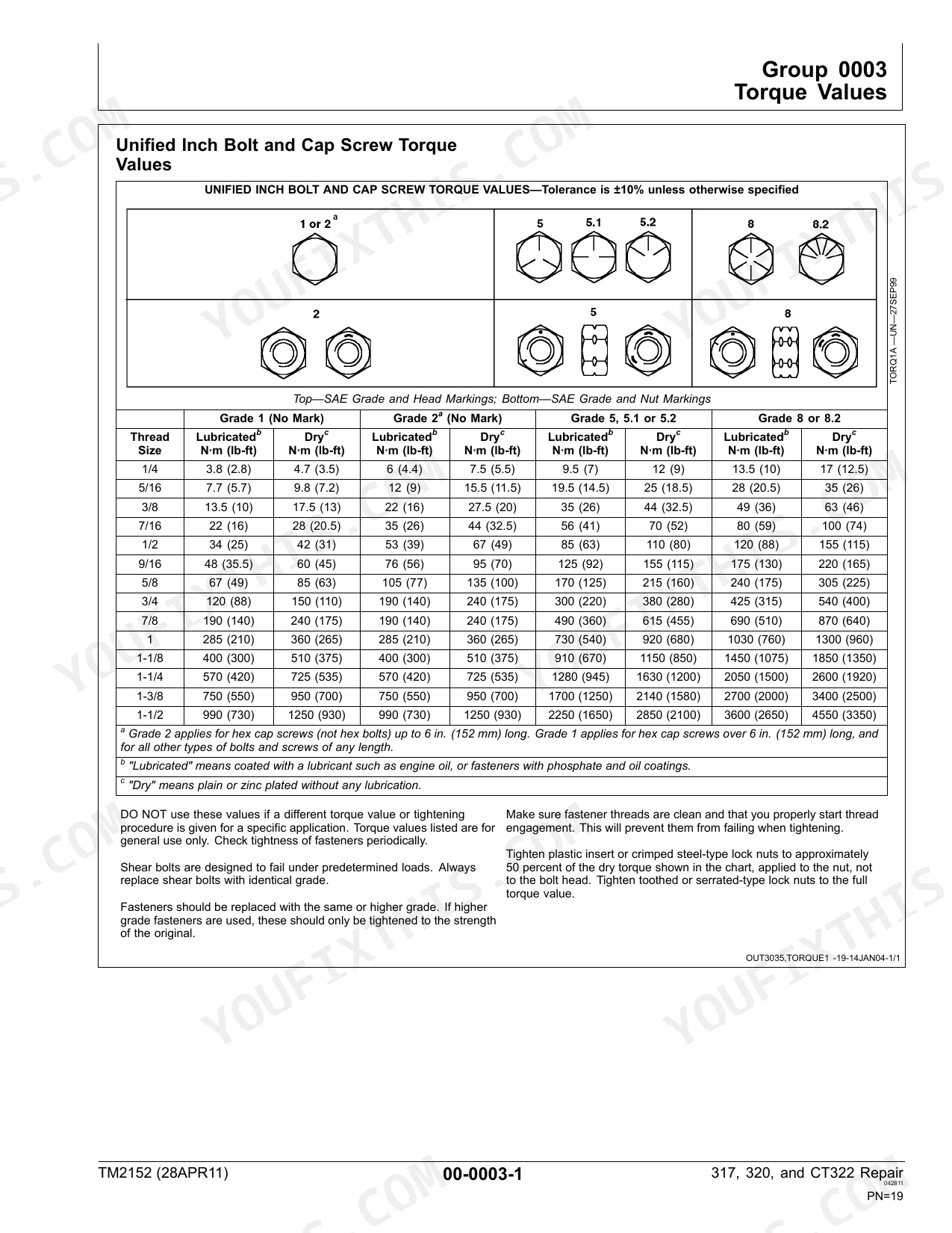
| General Information | 7-30 | Safety, Torque Values, Recognize Safety Information, Follow Safety Instructions, Operate Only If Qualified, Wear Protective Equipment, Avoid Unauthorized Machine Modifications |
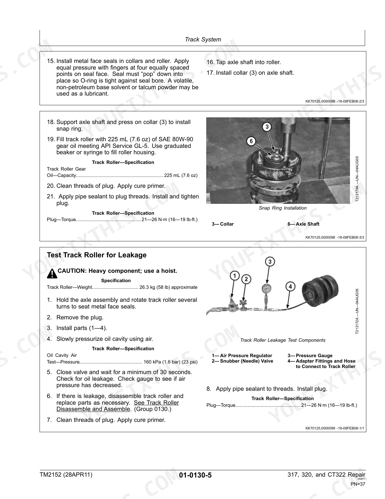
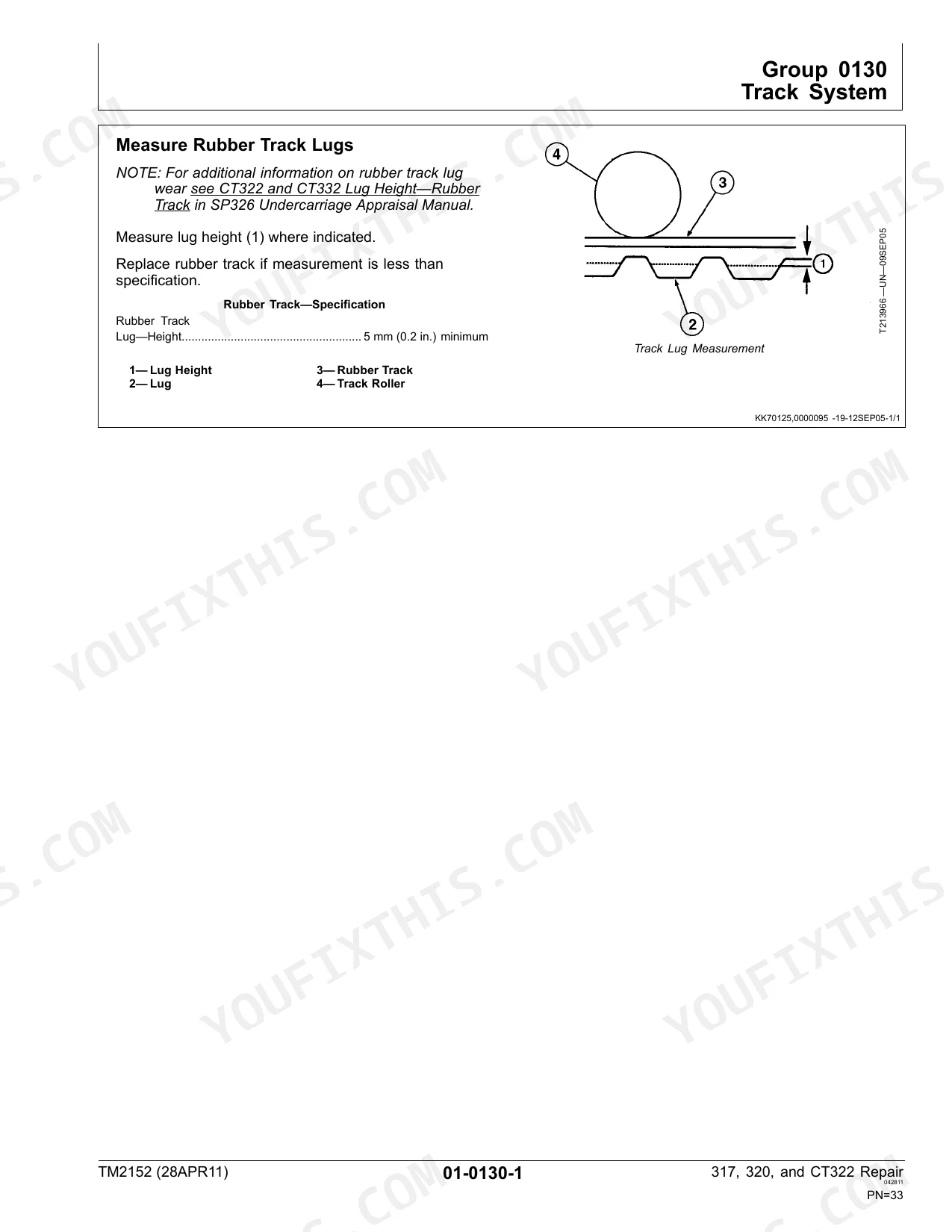
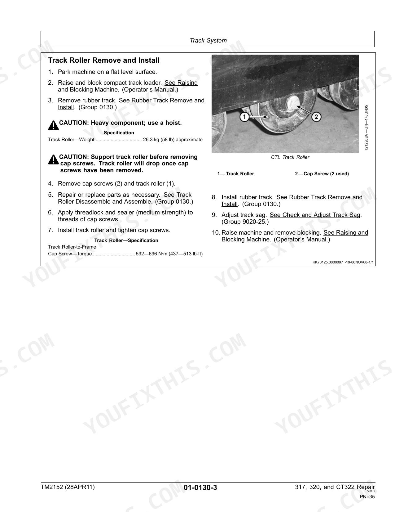
| Tracks | 31-48 | Track System, Measure Rubber Track Lugs, Rubber Track Remove and Install, Track Roller Remove and Install, Track Roller Disassemble and Assemble, Test Track Roller for Leakage |
| Axles and Suspension Systems | 49-58 | Axle Housing Remove and Install, Axle Housing Disassemble and Assemble, Chain Case Access Plate Remove and Install, Drive Chain and Sprocket Remove and Install |
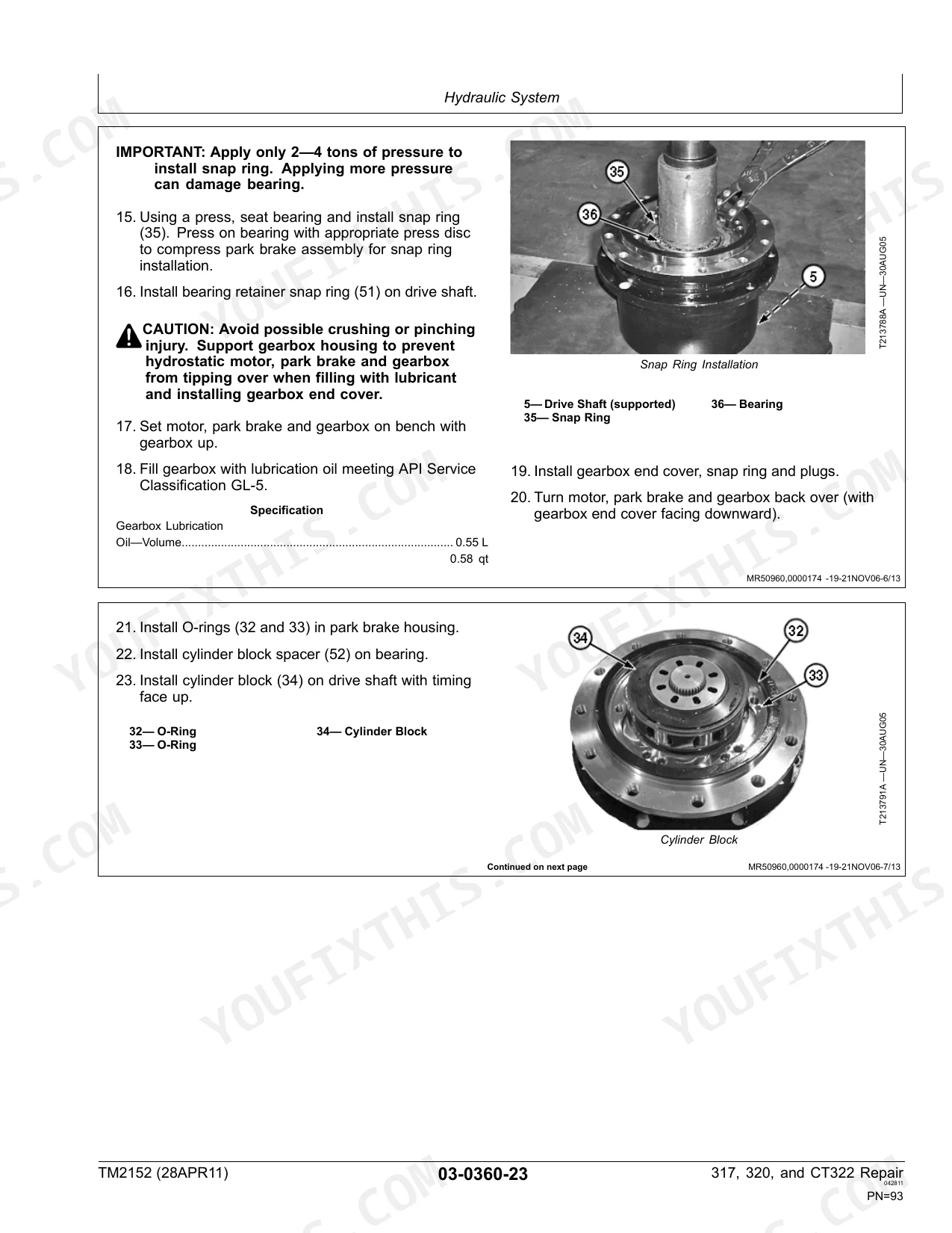
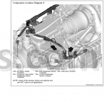
| Transmission | 59-122 | Controls Linkage (Centering Plate Remove and Install, Centering Plate Inspection, Steering Dampener Remove and Install, Steering Dampener Inspection, Steering Lever Remove and Install, Steering Lever Disassemble and Assemble, Steering Cross Shaft Assembly Remove and Install, Steering Cross Shaft Disassemble and Assemble, Steering Lever Handle Remove and Install), Hydrostatic Motor and Park Brake Disassemble and Assemble, Hub Coupler Remove and Install |
| Engine | 123-132 | Removal and Installation, Powertech 2.4 L & 3.0 L John Deere Engines, Engine Remove and Install, Alternator Remove and Install |
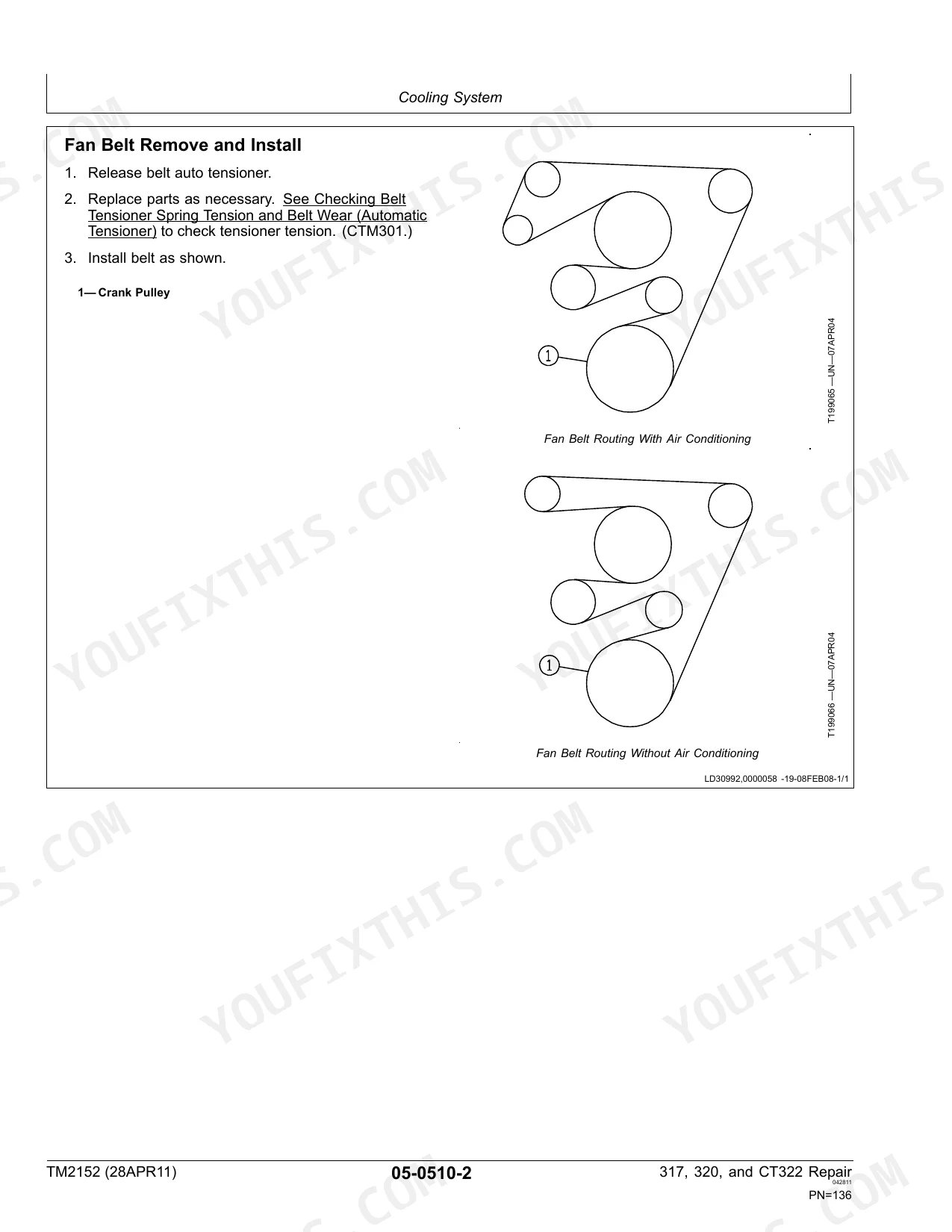
| Engine Auxiliary Systems | 133-142 | Cooling System (Radiator Remove and Install, Fan, Fan Guard, And Fan Shroud Remove and Install, Fan Belt Remove and Install) |
| Frame or Supporting Structure | 143-146 | Upper Boom Link Remove and Install, Lower Boom Link Remove and Install, Boom Remove and Install, Boom Lock Remove and Install |
| Operator's Station | 147-166 | Removal and Installation (Cab Remove and Install), Operator Enclosure (Cab Door Remove and Install), Seat and Seat Belt (Remove and Install, Belt Remove and Install) |
| Sheet Metal and Styling | 167-170 | - |
| Loader | 171-250 | Attachment Coupler (Quik-Tatch Coupler Remove and Install, Hydraulic Quik-Tatch Cylinder Remove and Install, Hydraulic Quik-Tatch Solenoid Valve Remove and Install, Electric Quik-Tatch Cylinder Remove and Install) |
| Dealer Fabricated Tools | 251-266 | DFT1101 Cab and ROPS Lift Bracket, DFT1245 Engine Lifting Bracket, ST4920 Track Recoil Spring Disassembly and Assembly Tool |
Quick Reference Specifications
| Specification | Value | Page |
|---|---|---|
| CT322 | ||
| Hydraulic Oil Filter Manifold Cap Screw—Torque | 18.5 N∙m (164 lb-in.) | p. 247 |
| Hydraulic Oil Filter Restriction Switch—Torque | 2.7—5.4 N∙m (24—48 lb-in.) | p. 247 |
| Replacement of parts | Repair or replace parts as necessary. | p. 247 |
| All Models | ||
| Charge Pressure—Pressure | 1965 kPa (19.6 bar) (285 psi) | p. 71 |
| Spool Lock Solenoid—Torque | 26—30 N∙m (19—22 lb-ft) | p. 224 |
| Port Lock Solenoid—Torque | 5—8 N∙m (44—71 lb-in.) | p. 224 |
| Cleanliness for hydrostatic motor internal surfaces | Maintain absolute cleanliness during assembly of the hydrostatic motor. | p. 77 |
| Unified Inch Bolt and Cap Screw Torque (1/4" Grade 5, Lubricated) | 9.5 N·m (7 lb-ft) | p. 19 |
| 317, 320 | ||
| Hydrostatic Motor—Weight | 48 kg (105 lbs) | p. 73 |
| Hydrostatic Motor Mounting Cap Screw—Torque (initial) | 70 N∙m (52 lb-ft) | p. 73 |
John Deere 317, 320, CT322 Common Problems This Manual Covers
Machine will not move
A skid steer or track loader that will not drive in either direction often traces back to low hydraulic oil or a charge pressure supply fault. The Transmission section covers the hydrostatic drive circuit and pressure checks needed to isolate the cause.
Manual Section: Transmission p. 59Boom and tilt drop while driving
Owners report the boom and bucket suddenly losing lift and tilt while the machine is moving, which points to a pressure loss rather than a control fault. Loader hydraulic and coupler service is documented in the Loader section.
Manual Section: Loader p. 171Drive motor failure contaminates hydraulics
A failing hydrostatic drive motor can shed debris into the whole hydraulic system, turning a single repair into a major cleanup. The Transmission section details motor removal, disassembly, and the cleanliness discipline required during reassembly.
Manual Section: Transmission p. 59Front lockout solenoid stalls machine
A machine that starts then dies shortly after, or throws start and run faults, commonly has a front lockout solenoid, wiring, fuse, or relay problem. Solenoid removal and torque values are covered in the Loader section.
Manual Section: Loader p. 171Rubber track and roller wear
Worn rubber track lugs and leaking track rollers are routine wear items on the CT322 undercarriage and cause vibration, poor traction, and uneven ride. The Tracks section covers measuring lug wear, roller removal, and leakage testing.
Manual Section: Tracks p. 31Cooling system overheating
Neglected radiators, worn fan belts, and clogged shrouds let these loaders run hot under load, risking engine damage. Radiator, fan, and fan belt service is documented in the Engine Auxiliary Systems section.
Manual Section: Engine Auxiliary Systems p. 133Frequently Asked Questions
Which machines does this manual cover?
TM2152 covers the John Deere 317 and 320 Skid Steer Loaders and the CT322 Compact Track Loader. It is the repair Technical Manual for these three models, built between 2003 and 2008.
Is this the repair manual or the operation and test manual?
This is the repair Technical Manual, TM2152. Its sections tell you how to remove, disassemble, inspect, and reinstall components. Operation and test diagnostics for these loaders are a separate John Deere publication (TM2151).
How do I release hydraulic pressure before servicing?
The manual specifies a Hydraulic System Pressure Release procedure before opening the hydraulic circuit, referenced in the Transmission section so you can safely relieve stored pressure before disconnecting lines. p. 71
What is the torque for the hydraulic filter manifold cap screws?
On the CT322, the hydraulic oil filter manifold cap screw torque is 18.5 N·m (164 lb-in.). This value and related manifold specs are listed in the Loader section. p. 247
How quickly can I access this John Deere 317, 320, CT322 manual after buying?
Download lands the moment you pay: a 266-page searchable PDF, no shipping and no waiting. It opens on any device, so you can pull it up on your phone right at the machine.
Is this John Deere 317, 320, CT322 Technical Manual printable?
Absolutely. No DRM or copy protection. Print the whole manual or just the pages you need. Any home or office printer works.


Reviews
There are no reviews yet.