
Part of the John Deere Repair Manuals.
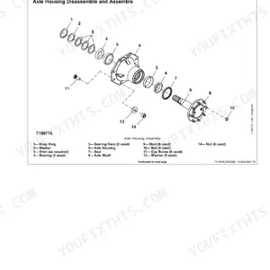
Looking to rebuild the drive axle on your skid steer? This 311-page John Deere 325, 328 repair manual pdf (OEM #TM2192) breaks down every engine removal, chain case access, and hydrostatic pump procedure. Open to a massive section of step-by-step rebuild instructions, complete with detailed exploded views of the final drives and loader boom links. You get exact system diagrams, refrigerant flush routines for the A/C, and page after page of factory torque values. Confirm your axle bearing rolling drag is set between 4.52 and 13.56 N·m, then lock down the upper boom pin cap screws to a solid 320 N·m. Guesswork leads to broken parts and blown budgets. Download the bookmarked file, type your component in the search bar, and get back to turning wrenches.
Complete the set for your 325, 328
- Parts Catalog: John Deere 325, 328 Skid Steer Parts Catalog
- Repair Manual: John Deere 325, 328 Operation and Test Manual — Wiring Diagrams
What's Inside This John Deere 325, 328 Repair Manual
| System | Pages | Key Topics |
|---|---|---|
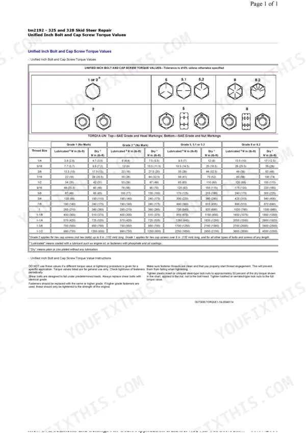
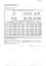
| General Information | 3-46 | Foreword, Safety Information, Torque Values, Chemical Product Handling, Waste Disposal |
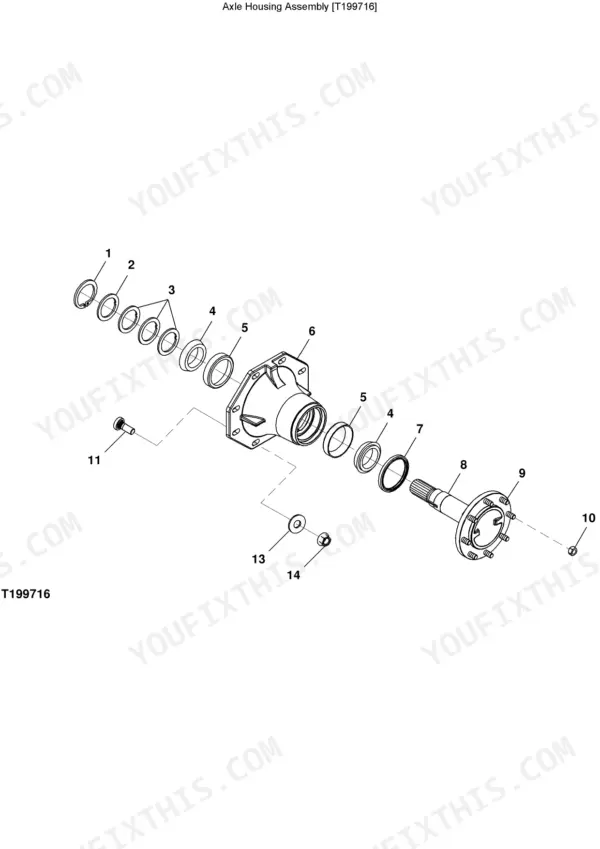
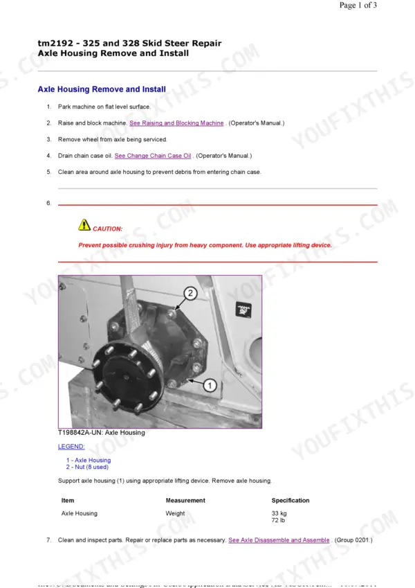
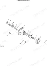
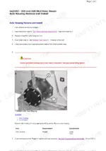
| Axles and Suspension Systems | 64-74 | Axle Housing Removal, Axle Housing Disassembly, Chain Case Access, Drive Chain & Sprocket |
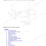
| Transmission | 75-139 | Steering Dampener, Steering Lever, Hub Coupler, Hydrostatic Pump, Park Brake Solenoid |
| Engine | 140-150 | Engine Removal, Radiator Hoses, Fuel Lines, Lifting Bracket |
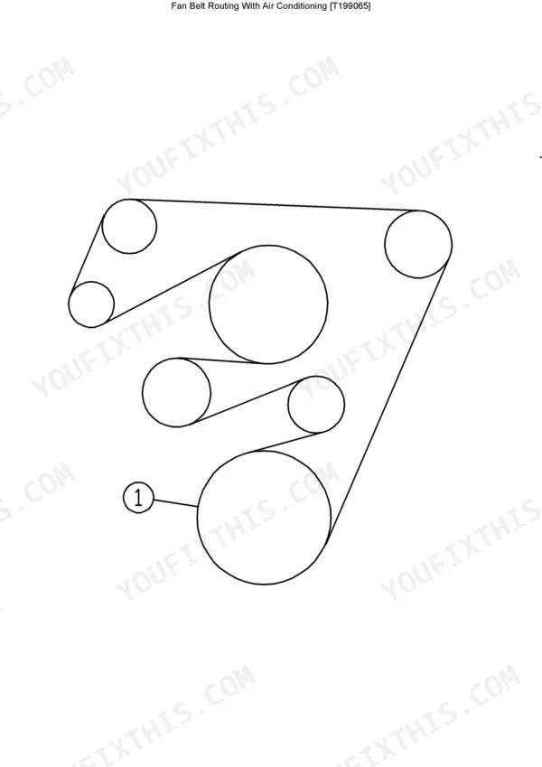
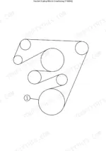
| Engine Auxiliary Systems | 151-166 | Alternator, Radiator, Fan & Shroud, Fan Belt, Engine Speed Control Linkage, Fuel Tank, Fuel Level Sensor |
| Frame or Supporting Structure | 167-178 | Welding Repair, Cab Removal, Cab Door, Seat Removal, Seat Belt |
| Heating and Air Conditioning | 179-198 | Refrigerant Cautions, Flush & Purge System, R134a Oil Information, Compressor Removal, Condenser Removal |
| Sheet Metal and Styling | 199-200 | Rear Door Removal, Hydraulic Oil Cooler Lines |
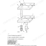
| Loader | 201-307 | Quik-Tatch Coupler, Hydraulic Quik-Tatch Cylinder, Pedal Assembly, Boom Link, Control Valve, Boom Cylinder, Hydraulic Oil Tank |
| Dealer Fabricated Tools | 308-311 | DFT1101 Cab and ROPS Lift Bracket, DFT1245 Engine Lifting Bracket |
Quick Reference Specifications
| Specification | Value | Page |
|---|---|---|
| Axle Bearing Rolling Drag Torque | 4.52–13.56 N·m 40–120 lb-in. | p. 69 |
| Upper Boom Link Weight | 97 kg 214 lb | p. 220 |
| Upper Pin Cap Screw Torque | 320 N·m 236 lb-ft | p. 221 |
| Hydraulic Pump Flange Cap Screw Torque | 60–65 N·m 44–48 lb-ft | p. 237 |
| Hydraulic Pump Gear Shaft Diameter | 19 mm 0.748 in. | p. 240 |
| Hydraulic Oil Filter Manifold Cap Screw Torque | 37 N·m 27 lb-ft | p. 303 |
| Hydraulic Oil Filter Restriction Switch Torque | 2.7—5.4 N·m 24—48 lb-in. | p. 303 |
| Taper Pin Cap Screw Torque | 620 N·m 460 lb-ft | p. 301 |
| Lower Pivot Pin Cap Screw Torque | 73 N·m 54 lb-ft | p. 301 |
| Axle Housing Weight | 33 kg | p. 64 |
| Axle Housing Capacity | 237 mL | p. 65 |
| Hydrostatic Motor Weight | 75 kg | p. 89 |
John Deere 325, 328 Common Problems This Manual Covers
John Deere 325 328 hydraulic pump loses power after warm-up, loader arms move sluggishly under load
Check the hydraulic pump drive gear splines and gear shaft on page 240; the shaft should measure 19 mm with the bushing bore at 19.2 mm. Inspect the wear plate and pump body gear pockets for scoring, then torque the flange cap screws to 60–65 N·m per page 237. Drain and replace the hydraulic oil filter before reinstalling.
Manual Section: Loader p. 240Engine stalls immediately or won't restart when loader arms are raised under a heavy load
Check the park brake disk pack height on page 119; disks should measure 30.4–30.6 mm before they're considered worn. If the brake drags and won't fully release, the engine bogs down and stalls when the boom loads the hydrostatic system. Inspect the shuttle valve spool and brake piston for sticking before condemning the motor.
Manual Section: Hydrostatic Motor and Park Brake—Two-Speed Disassemble and Assemble p. 119Axle bearings feel loose or grind, machine tracks unevenly and pulls to one side during turns
Measure axle bearing rolling drag torque on page 70; specification is 4.52–13.56 N·m. Readings outside this range point to worn or damaged bearings that let the axle shift under load, causing uneven tracking and side pull. Remove the axle housing, weighing roughly 33 kg, and inspect bearing races and seals for scoring or pitting before replacing.
Manual Section: Axles and Suspension Systems p. 70Loader arm pivot pins and bushings show excessive play, boom sags at full extension
Torque the upper pin cap screws on page 221 to 320 N·m; the lower pin cap screws share the same 320 N·m spec. If the boom still sags after retorquing, check the taper pin cap screws on page 301, torqued to 620 N·m, and the lower pivot pin cap screw at 73 N·m. Replace worn bushings rather than shimming the pins.
Manual Section: Loader p. 221Hydraulic oil filter clogs within days of replacement, restriction warning light stays on
Torque the hydraulic oil filter manifold cap screws on page 303 to 37 N·m and verify the restriction switch is torqued to 2.7–5.4 N·m; an over- or under-torqued switch triggers false warnings. If clogging is real, check upstream for contamination and drain the hydraulic oil tank before installing a new filter element.
Manual Section: Loader p. 303Frequently Asked Questions
How to reset hydraulic system on John Deere 325 328 skid steer?
The manual describes a "Hydrostatic and Hydraulic Start-Up Procedure" to remove air from the system. After connecting hydraulic lines, start the engine at half idle and operate steering, boom, and arm functions for 3 minutes. Stop the engine, check the hydraulic oil tank level, and repeat the operation for another 3 minutes to ensure air removal. p. 88
What are the replacement specifications for Hydraulic pump?
The High Flow Hydraulic Pump has no serviceable components and must be replaced as an assembly if any parts are worn or damaged. p. 248
What are the general torque values for unified inch bolts and cap screws on the John Deere 325 and 328 Skid Steer?
General torque values for unified inch bolts and cap screws vary by thread size and grade, and whether they are lubricated or dry. For example, a 1/4 inch Grade 5, 5.1 or 5.2 bolt requires 9.5 N·m (7 lb-ft) when lubricated and 12 N·m (9 lb-ft) when dry. Always refer to the detailed chart on page 40 for specific values, noting a ±10% tolerance unless otherwise specified. p. 40
What are the R134a refrigerant and oil capacities for the air conditioning system?
The total system volume for oil is 232 mL (7.85 fl oz), with a compressor precharge volume of 220 mL (7.43 fl oz). The R134a refrigerant weight is 1475 g (3.25 lb). If any section of hose is removed and flushed or replaced, add 3 mL of oil per 30 cm (0.1 fl oz per ft) of hose. p. 183
What is the specified charge pressure during the hydrostatic and hydraulic start-up procedure?
During the hydrostatic and hydraulic start-up procedure, the charge pressure should reach 1965 kPa (19.6 bar, 285 psi) within 5 to 10 seconds after starting the engine at slow idle with steering levers in neutral. If the charge pressure remains below 350 kPa (3.5 bar, 50 psi) for more than 10 seconds, stop the engine to prevent pump and motor damage.
What do I get after purchasing this John Deere 325 manual?
You get a 311-page searchable PDF that downloads instantly after checkout. Open it on your laptop, tablet, or phone, and bring it right to the shop floor.
Is this John Deere 325 Repair Manual printable?
Yes. Many mechanics print the section they need for their own shop and bring it to the bench.






Reviews
There are no reviews yet.