


Part of the John Deere Repair Manuals.
This is the complete John Deere factory technical manual for the 310SG and 315SG backhoe loaders. Across 1,306 pages it walks you through every major system on the machine: removing and servicing the diesel engine and torque converter, overhauling the powershift transmission, repairing the MFWD and rear axles, troubleshooting and repairing the main hydraulic system along with the dedicated loader and backhoe circuits, and tracing the full electrical system with wiring diagrams. It is the same information a John Deere dealer technician works from, with torque values, specifications and test pressures called out so repairs are done to spec the first time.
What's Inside This John Deere 310SG-315SG Repair Manual
| System | Pages | Key Topics |
|---|---|---|
| General | Safety Information, General Service Procedures | |
| Wheels | Powered and Non-Powered Wheels, Fastening Torques, Tire Removal and Installation | |
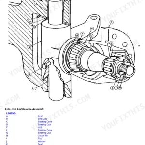
| Axles and Suspension | Drive Shafts, U-Joints, Non-Powered Front Axle, MFWD Powered Axle, Rear Axle, Bearings, Reduction Gears | |
| Transmission | Removal and Installation, Controls Linkage, Drive Shafts, Gears and Shafts, Bearings, Powershift Clutches, Hydraulic System | |
| Engine | Removal and Installation | |
| Engine Auxiliary Systems | Cold Weather Starting Aid, Cooling System, Speed Controls, Intake System, Exhaust System, External Fuel Supply System | |
| Torque Converter | Turbine, Gears and Shaft | |
| Steering System | Hydraulic Steering Circuit | |
| Service Brakes | Active Brake Elements, Hydraulic Brake System | |
| Park Brake | Park Brake Active Elements | |
| Electrical Systems | Batteries, Support and Cables, Alternator, Charging System Wiring, Wiring Harness and Switches, Instruments and Indicators, Motors and Actuators | |
| Frames and Chassis | Frame Installation, Chassis Weights | |
| Operator Station | Removal and Installation, Operator Enclosure, Seat and Seat Belt, Heating and Air Conditioning | |
| Sheet Metal and Styling | Hood and Engine Enclosure, Miscellaneous Shields, Grille and Grille Housing, Fenders | |
| Safety and Miscellaneous | Radio, Horn and Warning Devices | |
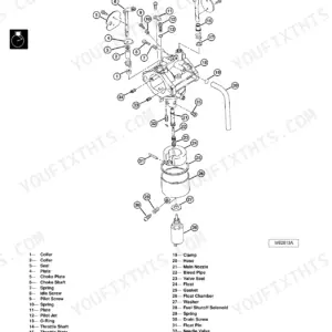
| Main Hydraulic System | Hydraulic System Components, Pumps, Valves, Lines | |
| Loader | Loader Assembly and Removal, Bucket, Control Linkages, Loader Hydraulic System | |
| Backhoe | Bucket, Control Linkage, Frames, Backhoe Hydraulic System | |
| Dealer Fabricated Tools | Special Service Tools and Fixtures |
Quick Reference Specifications
| Specification | Value | Page |
|---|---|---|
| All models | ||
| Drive Shaft Cap Screws Torque | 41 N.m (30 lb-ft) | |
| 310SG/315SG (S.N. -911131) | ||
| Wheel Bearing Castellated Nut Torque | 47 N.m (35 lb-ft) | |
| King Pin Lock Cap Screw Torque | 44 N.m (33 lb-ft) | |
| 310SG/315SG (S.N. 911132-) | ||
| Thrust Plate Cap Screws Torque | 120 N.m (89 lb-ft) | |
| Wheel Hub Cover Plug Torque | 15 N.m (11 lb-ft) | |
| Upper and Lower King Pin Cap Screws Torque | 120 N.m (86 lb-ft) | |
John Deere 310SG-315SG Common Problems This Manual Covers
Backhoe will not move any boom, stick, bucket or swing function despite a running pump
Confirm pilot oil supply to the backhoe directional control valve before condemning any individual valve. The Main Hydraulic System section covers testing pilot pressure at the DCV inlet; low or absent pilot pressure means the pilot supply valve or its solenoid is stuck or contaminated. Clean or replace the pilot supply valve, flush the circuit and re-test. If pilot pressure is normal, move to individual spool testing within the DCV per the backhoe hydraulic section.
Manual Section: Main Hydraulic SystemMachine cranks but will not start, suspected ECM or wiring fault
Begin with a physical inspection of wiring harness connectors and relay sockets under the chassis, as vibration-loosened pins and corroded contacts account for the majority of no-start codes on the SG. The Electrical Systems section covers harness routing, connector repair and ECM circuit testing. Verify glow plug function in cold conditions using the Engine Auxiliary Systems section before assuming an injection pump fault.
Manual Section: Electrical SystemsHydraulic system vibrates or chatters during operation
Cavitation from a misaligned pump coupling or air ingestion through a loose return fitting is the most common cause. Inspect the pump drive coupling alignment and check all hydraulic return line fittings for leaks or looseness that allow air ingestion. The Main Hydraulic System section covers pump removal and inspection, and the Engine Auxiliary Systems section covers pump drive alignment procedures.
Manual Section: Engine Auxiliary SystemsMachine runs but will not move in any gear
Start by checking loose electrical plugs and relays in the transmission control circuit before pulling the transmission, as disconnected connectors disable the powershift clutch solenoids and leave the machine stationary. Confirm battery voltage and alternator output are within spec per the Electrical Systems section. If electrical checks pass, the Transmission section covers the powershift clutch pack inspection, hydraulic circuit testing and full rebuild procedures.
Manual Section: TransmissionFrequently Asked Questions
Why does the 310SG/315SG backhoe not move any hydraulics even though the engine is running and the pump sounds normal?
This points to a pilot control system failure preventing oil from reaching the backhoe directional control valve. Check the pilot control supply circuit first: a stuck or contaminated pilot supply valve cuts off signal oil to all backhoe functions at once. The Main Hydraulic System section covers testing and disassembling the directional control valves and pilot circuit so you can isolate the fault before pulling the pump.
What causes a John Deere 310SG to crank but not start?
The most common causes on the SG are ECM signal faults, failed glow plugs on cold days, or a bad pump PWM signal to the fuel injection system. The Electrical Systems section covers the wiring harness, ECM circuits and glow plug circuits, and the Engine Auxiliary Systems section covers the fuel supply side so you can determine whether the fault is electrical or fuel-related before condemning the injection pump.
What are the key torque specs for the front axle and hub assemblies?
The Wheels and Axles sections list the grounded values: wheel bearing castellated nut at 47 N.m (35 lb-ft) for S.N. -911131 machines, thrust plate cap screws at 120 N.m (89 lb-ft) for S.N. 911132- machines, and drive shaft cap screws at 41 N.m (30 lb-ft). King pin cap screws run 44 N.m for the older serial range and 120 N.m for the newer. Always verify the serial break before torquing.
Why does the loader stabilizer fail to extend or retract?
Kinked or collapsed hoses and a blocked stabilizer control valve are the usual culprits. The Loader Hydraulic System section covers the stabilizer circuit, including how to test flow to the stabilizer valve and how to remove and inspect the valve body for contamination or worn seals.
Does this manual cover the full electrical and wiring system including the alternator?
Yes. Section 16 covers batteries, support and cables, the alternator and charging system wiring, the full wiring harness and switches, instruments and indicators, and motors and actuators. It has the wiring diagrams needed to trace intermittent faults such as loose relays under the chassis that cause no-move conditions.
How will I receive this John Deere 310SG, 315SG Repair?
Immediate download of the complete 1306-page searchable Repair (236 MB). Access it on any device, from a laptop at your desk to a phone in the field.
Am I able to print pages from this manual?
Zero restrictions. The PDF is DRM-free. Print whatever sections you need to take out to the shop. Standard letter or A4 paper works.


