
Part of the John Deere Repair Manuals.
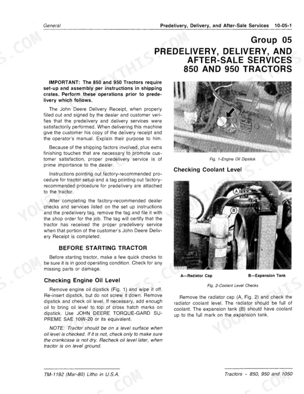
Need the factory-level John Deere 850 technical manual? This 818-page OEM document (TM1192) covers the 850, 900HC, 950, and 1050 Tractors from first bolt to final torque spec. Inside you get complete wiring diagrams for the charging, starting, and accessory circuits, plus hydraulic schematics covering the full rockshaft, selective control valve, and pressure relief system. A dedicated troubleshooting section walks through diagnosing clutch, transmission, PTO, power steering, and fuel injection malfunctions without guesswork. Fill the 850's crankcase to 4.5 L and the 950/1050 to 6.4 L, then verify compression sits between 3916 and 4405 kPa before you call the engine ready. Your machine is down. Download now and jump to any section by keyword or bookmark, not by scrolling 818 pages blind.
What's Inside This John Deere 850, 900HC, 950, 1050 Manual
| System | Pages | Key Topics |
|---|---|---|
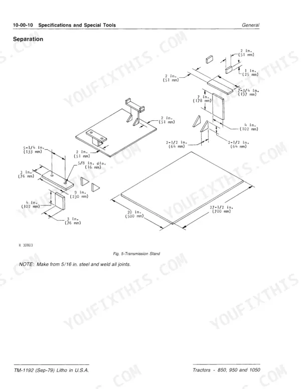
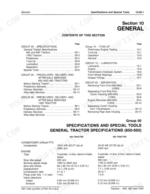
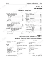
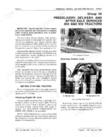
| General | 5-76 | Specifications, Special Tools, Predelivery Services, Tune-Up, Lubrication, Separation |
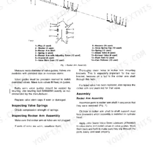
| Engine Repair | 77-148 | Cylinder Head, Valves, Camshaft, Cylinder Block, Liners, Pistons and Rods, Crankshaft, Main Bearings and Flywheel |
| Fuel and Air Repair | 149-188 | Air Intake System, Turbocharger, Diesel Fuel System, Fuel Injection Pump, Injection Nozzles, Speed Control Linkage |
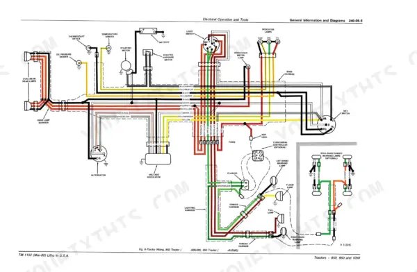
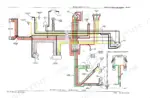
| Electrical Repair | 189-230 | Specifications, General Information, Charging System, Starting Circuit, Lighting and Accessory Circuits, Bulb Replacement |
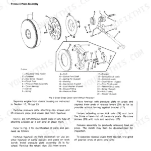
| Power Train Repair | 231-470 | Engine Clutch and Linkage, Sliding Gear Transmission, PTO, Differential, Final Drive |
| Steering/Brakes Repair | 471-514 | - |
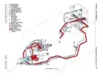
| Hydraulic Repair | 515-564 | - |
| Miscellaneous Repair | 565-578 | - |
| Operator Station Repair | 579-586 | Roll-Gard, Canopy, Seat Belts, Specifications, Special Tools |
| Engine Operation and Tests | 587-596 | System Operation, Lubrication System, Cooling System, Dynamometer Test, Diagnosing Engine Malfunctions, Checking Oil Pressure |
| Fuel/Air Operation and Tests | 597-624 | Air Intake System, Diesel Fuel System, Fuel Injection Pump, Injection Nozzles, Governor, Thermostart System |
| Electrical Operation and Tests | 625-658 | General Information, Charging System Diagnosis, Starting Circuit Diagnosis, Lighting and Accessory Circuits, Fuses, Battery |
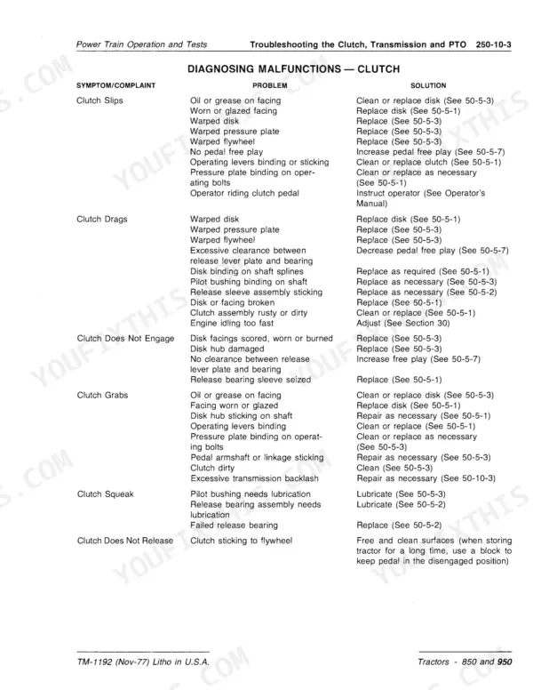
| Power Train Operation and Tests | 659-718 | Clutch, Transmission, PTO, Differential, Final Drive, Mechanical Front-Wheel Drive |
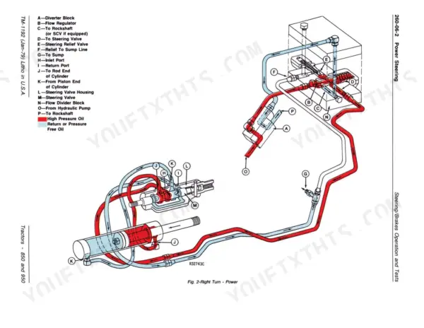
| Steering/Brakes Operation and Tests | 719-740 | Manual Steering, Power Steering, Flow Divider Block, Steering Relief Valve Test, Brakes, Diagnosing Malfunctions |
| Hydraulic Operation and Tests | 741-818 | Hydraulic System Operation, Hydraulic System Tests and Diagnosis, Hydraulic Pump, Rockshaft and Implement Hitches, Selective Control Valve, Pressure Relief Valve Operation |
Quick Reference Specifications
| Specification | Value | Page |
|---|---|---|
| 850 and 900HC | ||
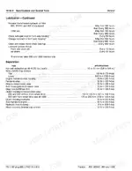
| Engine Oil Capacity (850 and 900HC) | 4.5 L (5 U.S. quarts) | p. 11 |
| 950 and 1050 | ||
| Engine Oil Capacity (950 and 1050) | 6.4 L (7 U.S. quarts) | p. 11 |
| MFWD Axle Housing Capacity | 8.5 L (8.9 U.S. quarts) | p. 11 |
| 850 (16001-), 950 (20001-), and 1050 | ||
| Transmission-Hydraulic System Capacity | 27 L (28.5 U.S. quarts) | p. 11 |
| All Models | ||
| Compression Pressure | 3916-4405 kPa (568 to 639 psi) | p. 11 |
| Radiator Cap Pressure Release | 98 kPa (14 psi) | p. 11 |
| Thermostat Opening Temperature | 71°C (160°F) | p. 11 |
| Engine Slow Idle Speed | 800 rpm | p. 11 |
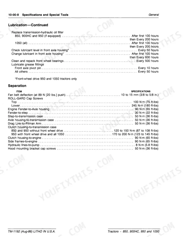
| Fan Belt Deflection (at 89 N [20 lbs.] push) | 10 to 15 mm (3/8 to 5/8 in.) | p. 12 |
| Clutch Housing-to-Engine Torque | 90 N·m (65 ft-lbs) | p. 12 |
| Hydraulic System Working Pressure | 13 790 kPa (2000 psi) | p. 6 |
| Engine Oil Change Interval | After first 50 hours then Every 100 hours | p. 11 |
John Deere 850, 900HC, 950, 1050 Common Problems This Manual Covers
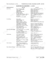
Transmission hard to shift between gears, or grinds when selecting a range
Check oil level in the transmission-hydraulic system before anything mechanical; low fluid thickens shift feel immediately. Inspect clutch adjustment and pedal free-travel — a dragging clutch (not fully releasing) is the leading cause of gear clash. Verify the clutch releases fully with the pedal fully depressed. If two speeds engage simultaneously, that points to a detent ball or shift fork issue; see the troubleshooting chart for the full decision tree.
Manual Section: Transmission MalfunctionsBattery warning lamp stays on at operating RPM, charging system not recovering
Test battery open-circuit voltage first, then verify alternator output with a multimeter at the battery terminals; charging voltage should rise above resting voltage at idle (800 rpm slow idle spec). Inspect the alternator belt for slippage — same deflection spec as the fan belt: 10 to 15 mm (3/8 to 5/8 in.) under 89 N (20 lbs.) force. Clean all ground connections at the block and frame. Charging circuit diagnostic sequence starts at page 629; wiring diagram is on page 633.
Manual Section: Electrical System Diagnosis p. 629Frequently Asked Questions
How do you fix john Deere 850 engine won't start or cranks slowly in cold weather?
Check the Thermostart system circuit first — verify the glow element heats within 30 seconds. Inspect battery terminals for corrosion and test battery under load; cold cranking requires full charge. Confirm fuel shutoff is open and bleed the injector lines if air has entered the system. Thermostat should begin opening at 71°C (160°F) — a stuck-open thermostat causes chronic cold-start trouble by keeping combustion temps low. p. 597
How do you fix engine overheats under load, temperature climbs past normal operating range?
Verify fan belt deflection first: push at center span with 89 N (20 lbs.) of force and confirm 10 to 15 mm (3/8 to 5/8 in.) of play. A loose belt cuts cooling airflow immediately. Flush the radiator and pressure-test the cap — it should release at 98 kPa (14 psi). Inspect the thermostat; opening temperature spec is 71°C (160°F). Check coolant level and look for combustion gas bubbles in the overflow, which signal a head gasket breach covered on page 592. p. 592
How do you fix hydraulic rockshaft lifts slowly or won't raise implement to full height?
Start with the suction screen: a partially blocked screen starves the pump before any other diagnosis is worth doing. Check transmission-hydraulic fluid level — system capacity on 850 (serial 16001-), 950 (serial 20001-), and 1050 is 27 L (28.5 U.S. quarts); low fluid is the single most common cause of slow lift. Then test main pump flow and verify system relief valve is holding 13 790 kPa (2000 psi). Step-by-step hydraulic test sequence begins.
How do you fix PTO engages but won't stay engaged, or disengages under load?
Inspect the PTO engagement linkage for wear or misadjustment before pulling covers. Check transmission-hydraulic oil level (27 L / 28.5 U.S. quarts on applicable models) — low oil causes PTO clutch pack slippage under load. Examine the PTO engagement detent and spring for fatigue. If the unit snaps out repeatedly under torque, suspect a worn clutch disc; repair procedures are in Power Train Repair starting page 231. Troubleshooting chart is.
What exactly do I receive with this John Deere 850 Technical Manual?
Instant PDF download. You get the full 818-page searchable Technical Manual immediately after payment. Open it on your laptop, tablet, or phone right in the shop.
Can I print this manual?
No restrictions at all. Print individual pages, full chapters, or the entire manual. The PDF is completely unlocked.
Are hydraulic system diagrams in this John Deere 850 Technical Manual?
Yes. The manual includes a hydraulic system diagram covering the main circuits.









Reviews
There are no reviews yet.