

Part of the John Deere Repair Manuals.
Looking for the factory teardown procedures for your crawler bulldozer? This 386-page John Deere 400G, TM-1412 repair manual PDF breaks down the entire transmission, undercarriage, and engine auxiliary systems. You get a massive section of exploded views showing exactly how the H-L-R clutch pack comes apart, plus step-by-step rebuilding instructions for the final drive and steering clutches. Open to the troubleshooting guides to diagnose track adjuster issues before you even pull a wrench. Adjust your track sag right the first time to 22.23-28.58 mm (7/8-1-1/8 in.) and verify your final drive pinion shaft preload matches factory numbers. Stop wasting time on guesswork when your dozer is sitting dead in the dirt. Download this bookmarked, searchable file to your tablet, find the exact spec, and get back to pushing dirt.
What's Inside This John Deere 400G Repair Manual
| System | Pages | Key Topics |
|---|---|---|
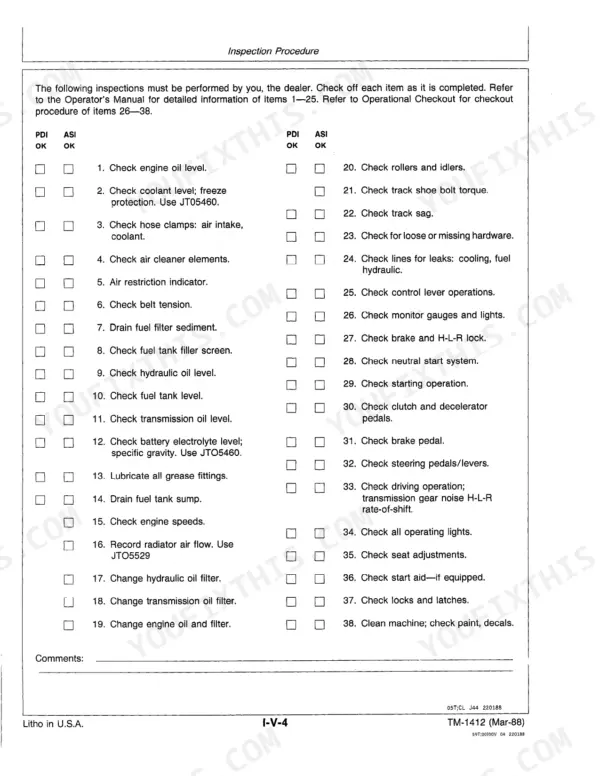
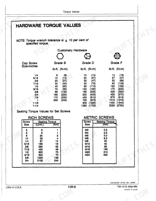
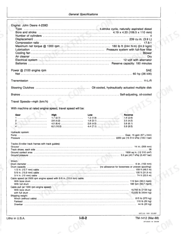
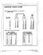
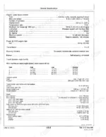
| General Information | Introduction and Safety, General Specifications, Torque Values, Fuels and Lubrication, Inspection Procedures | |
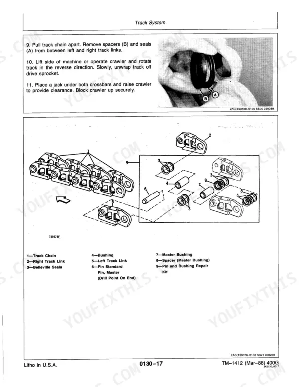
| Tracks | Track Chain, Track Frame, Track Rollers, Front Idler, Track Adjuster, Sprockets | |
| Axles and Suspension Systems | Axle Shaft, Bearings, Reduction Gears, Final Drive Removal, Steering Clutch and Brake Band | |
| Transmission | Controls, Gears, Shafts, Bearings, H-L-R Clutch, Hydraulic System, Oil Filter Base Assembly | |
| Engine | Removal and Installation, Cylinder Head, Crankshaft, Pistons, Camshaft | |
| Engine Auxiliary Systems | Cold Weather Starting Aid (Starting Aid Solenoid and Nozzles), Cooling System (Fan Belt, Blower Fan, Radiator, Oil Cooler, Pump and Radiator Support) | |
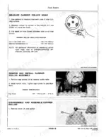
| Clutch | Assemble High Range Clutch, Disassemble Low and Reverse Clutch, Assemble Low and Reverse Clutch, Assemble H-L-R Clutch Pack Assembly, Disassemble Clutch Accumulator Valve | |
| Steering System | Hydraulic System (Specifications, Steering Valve Spools, Remove and Install), Specifications, Remove and Install Steering Valve Spools, Check Diameter of Valve Spool | |
| Equipment Attaching | Fairlead (Winch Fairlead, Disassemble and Assemble), Disassemble and Assemble Winch Fairlead, Inspect Top Roller and Each Side Roller for Excessive Wear or Damage | |
| Electrical System | Batteries, Alternator, Regulator, Charging System, Lighting System, Wiring Harness and Switches, Instruments and Indicators, Motors and Actuators | |
| Frame, Chassis, or Supporting Structure | Frames, Side Frames Removal, Torque Specifications | |
| Operator's Station | Operator Enclosure, ROPS Removal, Seat and Seat Belt | |
| Sheet Metal and Styling | Hood and Engine Enclosure (Service Equipment and Tools, Specifications, Grille Housing, Remove and Install, Cowl), Service Equipment and Tools | |
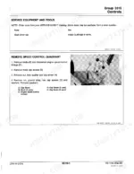
| Winch | Essential Tools, Service Equipment and Tools, Other Materials, Specifications, Winch Repair, Remove Brake Band and Cylinder, Disassemble and Assemble Brake Cylinder | |
| Bulldozer | Blades, Controls Linkage, Frames, Hydraulic System, Lift and Angle Cylinders, Tilt Cylinders | |
| PTO or Winch Drive | Gears, Shafts and Bearings (Special Tools, RPM Powershaft and Winch Drive, Remove, Disassemble and Inspect, Assemble, Install), Service Equipment and Tools | |
| Ground Conditioning Tools | Teeth and Shanks, Frame, Hydraulic System (Ripper Cylinder), Section 09, Steering System (Hydraulic System, Steering Valve Spools) | |
| Dealer Fabricated Tools | Final Drive Positioning and Lifting Tool, Spring Tool, Alignment Stud, Special Wrench |
Quick Reference Specifications
| Specification | Value | Page |
|---|---|---|
| Track Adjuster | Adjustment | p. 3 |
| Final Drive | Repair | p. 3 |
| Power Shift Clutches | Repair | p. 3 |
| Steering Clutch | Repair | p. 3 |
| Track Sag | 22.23-28.58 mm (7/8-1-1/8 in.) | p. 58 |
| Final Drive Pinion Shaft Preload | 0.00-0.08 mm (0.00-0.003 in.) | p. 81 |
| Axle Rotation (New Bearings) Rolling Torque | 10-13 N·m (90-115 lb-in.) | p. 81 |
| Steering Clutch Housing-to-Brake Drum Cap Screws Torque | 40 N·m (30 lb-ft) | p. 56 |
| Steering Clutch Housing-to-Transmission Case Cap Screws 5/8 in. Torque | 210 N·m (155 lb-ft) | p. 82 |
| Clutch Accumulator Valve-to-Clutch Oil Manifold Cap Screws | 27 N·m (20 lb-ft) | p. 110 |
| Clutch Control Valve Spring Free Length (approximate) | 21.5 mm (.84 in.) | p. 112 |
| Transmission Oil Filter Assembly Spring Free Length (approximate) | 78 mm (3.06 in.) | p. 112 |
John Deere 400G Common Problems This Manual Covers
John Deere 400G reverse and Low gear won't engage while High gear works fine
Measure the clutch control valve spring free length against the page 112 spec: 21.5 mm (.84 in.), testing at 15.2 mm (.60 in.) under 115.7 N ± 13 N. A collapsed spring stops Low and Reverse engagement; replace if undersized. Confirm accumulator valve-to-oil manifold cap screws are torqued to 27 N·m (20 lb-ft) per page 110.
Manual Section: Clutch p. 112Uneven steering or the machine pulls hard to one side on level ground
Torque the final drive housing-to-steering clutch housing upper cap screws to 210 N·m (155 lb-ft) per page 82; loose bolts let the clutch pack slip and pull the machine to one side. Inspect the steering clutch and brake band for uneven lining wear, and confirm track sag matches 22.23-28.58 mm (7/8-1-1/8 in.) on both sides per page 58.
Manual Section: Steering Clutches and Brakes Adjustment p. 82Loss of hydraulic pressure and sluggish, weak blade lift response when dozing under load
Test the control valve relief valve setting; spec calls for 6550-7240 kPa (950-1050 psi) at 68-74°C (155-165°F) with the engine at 1900 rpm, per page 313. Low pressure points to worn pump gears; check gear width against 9.51-9.52 mm (0.3745-0.3750 in.) and replace if undersized. Torque hydraulic pump cap screws to 54-68 N·m (40-50 lb-ft) per page 343 on reassembly.
Manual Section: Bulldozer p. 313Track sag out of spec or track slapping over the rollers during travel
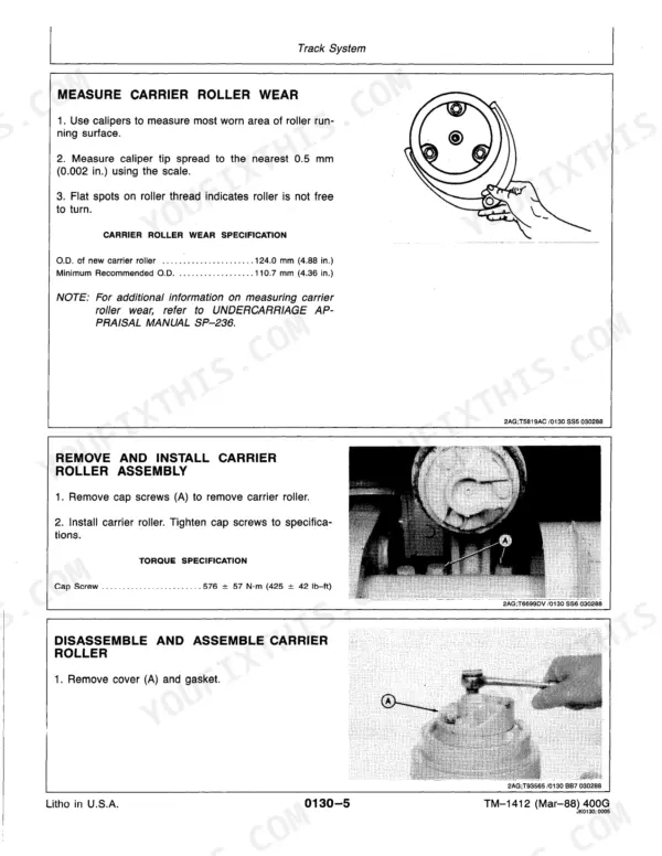
Measure track sag at the idler; spec is 22.23-28.58 mm (7/8-1-1/8 in.) per page 58, and readjust the track adjuster if out of range. If sag returns quickly after adjustment, check carrier roller and track bushing wear. Torque track shoe attaching cap screws to 149 N-m (110 lb-ft) per page 56 during reassembly to stop shoe walking.
Manual Section: Track Sag Adjustment p. 58Engine won't start or cranks slowly in cold weather despite a fully charged battery
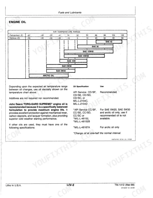
Load test the battery against the page 231 spec of 570 cold cranking amps at -18°C (0°F), and replace it if it fails under load. Verify the thermostat begins opening at 80-85°C (177-184°F) per page 181 to confirm warm-up. Check the cold weather starting aid solenoid and nozzles, and fill engine oil to the 8.5 qt capacity per page 15.
Manual Section: Electrical System p. 231Frequently Asked Questions
What are the torque specifications for John Deere 400G track shoe cap screws?
The torque specification for John Deere 400G track shoe cap screws is 149 N-m (110 lb-ft). This torque should be applied using a criss-cross sequence, and checked after 50-100 hours of operation to ensure tightness. p. 47
How can issues with John Deere 400G reverse and low gear engagement be addressed?
Issues with slow or no engagement in reverse and low gear on the John Deere 400G can be addressed by adjusting the H-L-R shift linkage and engine clutch valve. Excessive play in the H-L-R shift linkage or clutch pedal free travel below 89 mm (3-1/2 in.) may cause these symptoms, and adjustment procedures are detailed on pages 106 and 173. p. 106
What is the engine oil capacity for the John Deere 400G, including the filter?
The engine oil capacity for the John Deere 400G, including the filter, is 8.0 L (8.5 qt). This information is found in the "Drain and Refill Capacities" section of the manual. p. 15
What is the cooling system capacity for the John Deere 400G?
The cooling system capacity for the John Deere 400G is 12.3 L (3.5 gal). This specification is listed under "Drain and Refill Capacities" in the general specifications. p. 15
What is the specified torque for the John Deere 400G engine-to-clutch housing cap screws?
The specified torque for the John Deere 400G engine-to-clutch housing cap screws is 230 N-m (170 lb-ft). This torque value is crucial for proper assembly and can be found in the "Specifications" section for the engine. p. 181
Will this John Deere 400G Repair Manual download right away?
Immediate download of the complete 386-page searchable Repair Manual. Access it on any device, from a laptop at your desk to a phone in the field.
Does this John Deere 400G manual allow printing?
Yes. Print a chapter or just the pages for the job at hand, for use in your own shop. Any home or office printer works.








Reviews
There are no reviews yet.