


Part of the John Deere Repair Manuals.
This is the complete John Deere factory Operation and Tests manual (TM2234) for the 7630, 7730, 7830 and 7930 tractors. Across 5,247 pages it covers theory of operation and step-by-step diagnostic test procedures for every system on the machine: how to read and clear diagnostic trouble codes, how to use observable symptom trees to find the root cause without guessing, and how to run pressure, flow and electrical tests on the engine, transmissions, hydraulics and control units. It is the companion volume to the Repair manual - where the Repair manual shows how to rebuild components, this manual tells you which component is at fault and how to confirm it with a test before you start taking things apart.
What's Inside This John Deere 7630-7930 Manual
| System | Pages | Key Topics |
|---|---|---|
| General | Safety Precautions, Specifications, Torque Values, Lubricants and Fluids, Service Intervals, Special Tools List | |
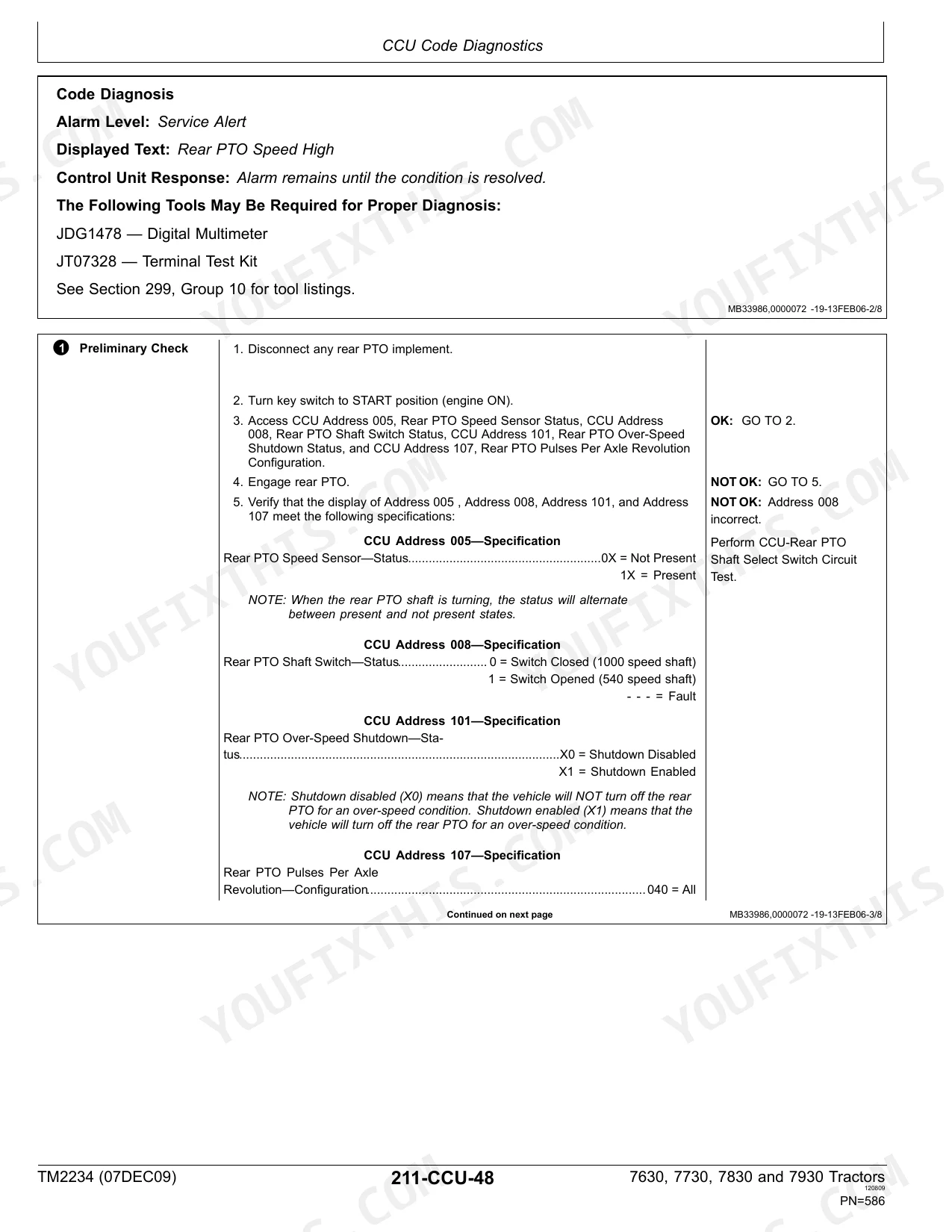
| Diagnostic Trouble Codes | Full Dtc List, Error Code Definitions, Fault Severity Levels, Acu and ECU Code Tables, Resetting Procedure | |
| Observable Symptoms | Symptom-Based Diagnostic Trees, Engine Performance Faults, Transmission Symptoms, Hydraulic Symptoms, Electrical Symptoms | |
| System Diagnosis | Component Testing Procedures, Circuit Diagnosis Flow Charts, CAN Bus Diagnosis, Diagnostic Equipment Use | |
| Engines | Engine Theory of Operation, Oil Pressure Tests, Compression Tests, Cooling System Tests, Turbocharger Diagnosis | |
| Fuel and Air Intake Systems | Common-Rail Fuel System Theory, Fuel Pressure Tests, Injection System Diagnosis, Air Intake Restriction Tests, Water Separator Service | |
| Electrical | Wiring Harness Tests, Electrical Component Diagnosis, Voltage Drop Testing, Circuit Load Testing, Harness Connector Inspection | |
| Control Units | Acu Operation, CAN Bus Communication, ECU Power and Ground Tests, Control Unit input/output Diagnosis, Software Codes | |
| AutoPowr / IVT Transmission | IVT Theory of Operation, Transmission Pressure Tests, Clutch Pack Diagnosis, Control Valve Testing, Hydrostatic Circuit | |
| PowrQuad Plus and AutoQuad Plus Transmission | PowrQuad Shift Quality Tests, AutoQuad Clutch Diagnosis, Transmission Oil Pressure, Clutch Timing Tests | |
| Drive Systems | MFWD Theory and Tests, Differential Lock, Final Drive Diagnosis, Front Axle Tests | |
| Steering and Brakes | Steering System Theory, Steering Pressure Tests, Brake Pedal Adjustment, MFWD Brake Diagnosis | |
| Hydraulics | Hydraulic System Theory, Pump Flow and Pressure Tests, Selective Control Valve Testing, Three-Point Hitch Diagnosis, Load Sensing Circuit | |
| Operator Station | CommandCenter Operation, Instrument Cluster, HVAC System, Armrest Controls, Seat and Visibility | |
| Service Tools | Special Service Tools, Diagnostic Scan Tools, Test Equipment List, Pressure Gauges and Flow Meters |
Quick Reference Specifications
| Specification | Value | Page |
|---|---|---|
| All models | ||
| Supply Voltage (Battery) | 12.5 - 14.5 V | |
| ACU system | ||
| ACU System Voltage Low Range | 12.50 V | |
| ACU System Voltage High Range | 14.50 V | |
| All control units | ||
| Control Unit Power Input Voltage | Within 1 V of battery voltage | |
| Control Unit Ground Circuit Resistance | Less than 1.0 ohm | |
| Electrical circuit testing | ||
| Voltage Drop per Connection (max) | 0.1 to 0.2 V | |
| Excessive Resistance Voltage Drop Threshold | Greater than 0.4 V | |
| ACU / transmission cold-start protection | ||
| Engine Speed Limit (cold transmission below -5 C / 23 F) | 1500 rpm | |
| Electrical test equipment | ||
| DFRW51 Circuit Load Tester - Current Draw | 3.8 to 4.2 amps | |
| Digital multimeter continuity checks | ||
| Continuity Test Resistance Threshold | Less than 150 ohms | |
John Deere 7630-7930 Common Problems This Manual Covers
ACU communication faults causing F5 error or system-wide warning messages
Inspect the 8-pin electrical connector at the armrest for corrosion and pushed-back pins before condemning the ACU. Test ACU supply voltage (12.5-14.5 V) and ground resistance (below 1.0 ohm) as outlined in the Control Units section. Check the CAN bus terminator resistors at both ends of the bus - these fail on high-hour machines and generate spurious communication DTCs across multiple control units.
Manual Section: Control UnitsEngine loses power under load with rail pressure fault code (such as code 1347.07)
Work through the Fuel and Air Intake Systems test sequence before touching injectors or the high-pressure pump. Replace the fuel water separator filter (RE52504) and primary fuel filter, then run the fuel pressure test at the lift pump outlet. Low lift pump pressure starves the high-pressure pump and produces rail pressure codes that look like injection pump failure but are actually a cheap filter service job.
Manual Section: Fuel and Air Intake SystemsTransmission not responding to commands, with transmission DTC displayed on CommandCenter
Pull the active DTCs using the CommandCenter diagnostic menu and cross-reference them in Section 211. The System Diagnosis section then directs you to the specific circuit test for the fault. On these tractors, transmission DTCs are often triggered by a CAN bus issue rather than a mechanical fault - verify CAN bus integrity first using the resistance test between CAN-H and CAN-L before opening the transmission.
Manual Section: Diagnostic Trouble Codes / System DiagnosisIntermittent electrical faults, corroded connectors or multiple simultaneous error codes
Multiple simultaneous DTCs across systems usually point to a shared supply, ground or CAN bus fault rather than individual component failures. The Electrical section covers voltage drop testing (acceptable limit 0.1-0.2 V per connection; above 0.4 V indicates excessive resistance) and the circuit load tester procedure using the DFRW51 tool. Inspect harness routing points for chafing and pay particular attention to the under-hood connectors and the main ground strap to the engine block.
Manual Section: ElectricalFrequently Asked Questions
What is the OEM number for the John Deere 7630 7730 7830 7930 Operation and Tests manual?
The factory manual number is TM2234. This Operation and Tests manual covers all four models in the 7030 Series and is a separate volume from the Repair manual. When ordering or verifying you have the right document, confirm the TM2234 designation on the cover or title page.
How do I diagnose an ACU communication fault or F5 error on a John Deere 7830?
ACU faults are among the most common issues on these tractors. The Control Units section covers how to test ACU power supply (should read 12.5-14.5 V) and ground circuits (less than 1.0 ohm). Start by inspecting the 8-pin armrest connector for corrosion, then use the DTC section to look up the specific code. A failed ACU or corroded CAN bus terminator causes the majority of these communication errors.
What causes low engine power with a rail pressure fault code on a John Deere 7830 or 7930?
Code 1347.07 and related rail pressure codes point to the common-rail fuel system. The Fuel and Air Intake Systems section walks through fuel pressure tests, injector leak-off checks and water separator inspection. Before assuming an injector or high-pressure pump failure, verify the fuel water separator is not plugged and that the primary filter has been serviced on schedule.
How do I run a hydraulic pressure test on a John Deere 7630 or 7930?
The Hydraulics section covers the theory of the load-sensing hydraulic system and gives step-by-step pressure and flow test procedures for the main pump, selective control valves and three-point hitch circuit. You will need a flow meter and pressure gauges - the Service Tools section lists the factory test equipment and part numbers. Test pressures and acceptable flow ranges are called out in the test procedures.
What is the difference between this Operation and Tests manual and the John Deere 7630-7930 Repair manual?
This TM2234 manual covers theory of operation and diagnostic test procedures - it tells you which component is faulty and how to confirm it before disassembly. The Repair manual covers how to remove, rebuild and reinstall components once you know what needs fixing. Technicians use both: Operation and Tests first to identify the fault, then the Repair manual to correct it.
How quickly can I access this manual after?
Immediate download of the complete 5247-page searchable Operation and Tests (150 MB). Access it on any device, from a laptop at your desk to a phone in the field.
Can I print specific sections of this manual?
Yes, print as many copies as you want, and there are no restrictions. Many mechanics print the section they need and bring it to the shop floor.


Reviews
There are no reviews yet.