


![John Deere Model R Diesel Repair Manual [Tractor]](https://youfixthis.com/wp-content/uploads/2012/02/Manual_Download-300x300.jpg)
Part of the John Deere Repair Manuals.
This is the John Deere factory diagnostics manual (TM4726) for the 6020, 6120, 6220, 6320, 6420, 6420S, 6520, 6620, 6820, 6920 and 6920S tractors. Across 1,496 pages it covers every electronic control unit, all diagnostic trouble codes, observable symptom trees and step-by-step system diagnostics for the engine, electrical system, all four transmission types (SyncroPlus, Power Reverser, AutoPowr/IVT and PowrQuad), drive systems, steering, hydraulics and the operator cab. It is the same reference John Deere dealer technicians use alongside Service Advisor, giving you the voltage specs, resistance values and symptom trees to trace a fault to its root cause.
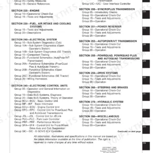
What's Inside This John Deere 6020, 6120, 6220, 6320, 6420, 6420S, 6520, 6620, 6820, 6920, 6920S Manual
| System | Pages | Key Topics |
|---|---|---|
| General Information | Safety Precautions, Diagnostic Tool Usage, Dtc Reading and Clearing Procedures, System Component Locations, Electrical Measurement Basics | |
| Diagnostic Trouble Codes | Atc, Bcu, Bif, ECU, Epc, Jdl, Plc, Prf, Sfa, Sic, Ssu, Tcu, Tec, Uic Controller Fault Codes with Descriptions and Corrective Actions | |
| Observable Symptoms | Engine Symptoms, Transmission Shift Symptoms, Hydraulic Symptoms, Electrical and Instrument Panel Symptoms, PTO Engagement Symptoms | |
| Engine | No-Start Diagnosis, Fuel Delivery Testing, Cooling System Faults, Oil Pressure Fault Codes, Injector Pump Diagnostics | |
| Electrical System | System Voltage Tests (11.2-15.4 V Range), Battery Diagnostics, Alternator Tests, Wiring Harness Inspection, Solenoid Valve Resistance and Current Checks | |
| Electronics | CAN Bus Communication Diagnostics, Controller Area Network Faults, Sensor Diagnostics, Isobus and JDLink Interface | |
| SyncroPlus Transmission | Gear Engagement Faults, Clutch Diagnostics, Shift Quality Symptoms, SyncroPlus Dtc Interpretation | |
| Power Reverser Transmission | Reverser Clutch Diagnostics, forward/reverse Engagement Faults, Prc Fault Code Procedures | |
| AutoPowr/IVT Transmission | Infinitely Variable Transmission Diagnostics, Hydrostatic Unit Faults, IVT Warning Light Procedures, 6420S/6520/6820/6920S Specific | |
| PowrQuad, PowrQuad Plus and AutoQuad Transmissions | Power Shift Clutch Faults, AutoQuad Shift Diagnostics, PowrQuad Plus Dtc Procedures | |
| Drive Systems | Front Axle 4WD Engagement Diagnostics, Differential Lock Solenoid Tests (10-12 Ohm, 1-1.2 a), Front Axle Clutch Faults | |
| Steering and Brakes | Hydraulic Steering Diagnostics, Brake Pressure Sensor Tests, Steering Fault Code Procedures | |
| Hydraulic System | Hydraulic Pump Diagnostics, Valve Block Fault Isolation, Pressure Testing, Remote Cylinder Diagnostics, Load-Sensing Circuit Tests | |
| Operator's Cab | Instrument Panel Diagnostics, CommandCenter Monitor Faults, Air Conditioning System Diagnostics, Sfa and Sic Control Diagnostics |
Quick Reference Specifications
| Specification | Value | Page |
|---|---|---|
| System Voltage (Ignition ON, engine OFF) | 11.2 - 12.7 volts | |
| System Voltage (Engine running, low idle) | 11.2 - 15.4 volts | |
| System Voltage (Engine at 1500 rpm) | 12.5 - 15.4 volts | |
| Rear PTO Solenoid Supply Voltage (disengaged) | 0 volts | |
| Rear PTO Solenoid Supply Voltage (engaged) | 12 volts | |
| Differential Lock Solenoid Valve Resistance | 10 - 12 ohms at 20 degrees C | |
| Differential Lock Solenoid Voltage (disengaged) | 0 volt | |
| Differential Lock Solenoid Voltage (engaged) | 12 volts | |
| Differential Lock Solenoid Amperage (engaged) | 1 - 1.2 amps at 20 degrees C and 12-volt nominal | |
| Front PTO Solenoid Supply Voltage (disengaged) | 0 volts | |
| Front PTO Solenoid Supply Voltage (engaged) | 12 volts |
John Deere 6020, 6120, 6220, 6320, 6420, 6420S, 6520, 6620, 6820, 6920, 6920S Common Problems This Manual Covers
Engine fails to start or stalls immediately after cranking with an ECU fault code
Work through the Engine diagnostics group, starting with fuel delivery - check the fuel filter and water separator for contamination before suspecting the injection pump. The manual covers the no-start symptom tree, fuel pressure testing at the injection pump inlet and the ECU fuel-related fault code paths so you can isolate the failed component using measured results rather than guesswork.
Manual Section: System Diagnostics - Engine (Group 20)Multiple warning lights on the instrument panel with the tractor entering limp or reduced-function mode
Read all active and stored DTCs via Service Advisor before touching anything. The Diagnostic Trouble Codes section lists every code across the BCU, ECU, TCU and other controllers with a description and next-step path. A single failed sensor can cascade three to five warning lights; clearing codes and verifying which return after a re-start confirms the real fault vs secondary alarms.
Manual Section: Diagnostic Trouble Codes (Section 211)Hydraulic system loses pressure after two to three hours of continuous operation
The Hydraulic System diagnostics section covers pressure testing the main pump, the priority valve and the load-sensing circuit with step-by-step measurement points. Replace the hydraulic filter and inspect the return circuit for restriction first. A pump losing pressure under sustained load is often worn rather than failed outright; the manual gives the minimum acceptable pump output pressure so you can confirm pump condition before removal.
Manual Section: System Diagnostics - Hydraulic System (Group 70)Front axle 4WD fails to engage or engages with a jolt and fault code
The Drive Systems diagnostics group covers the front axle engagement clutch and the 4WD solenoid valve. Measure the solenoid supply voltage (0 V disengaged, 12 V engaged) and resistance as specified in the Electrical System group, then follow the Drive Systems symptom tree to isolate whether the fault is in the solenoid circuit, the hydraulic engagement valve or the clutch pack itself.
Manual Section: System Diagnostics - Drive Systems (Group 56)Frequently Asked Questions
How do I read and clear diagnostic trouble codes on a John Deere 6020 to 6920S tractor?
Connect John Deere Service Advisor through the diagnostic port. Section 211 lists every active and stored DTC for all controllers - ECU, BCU, TCU, ATC and others - with a plain description and the corrective action path. After fixing the root fault, clear codes through the instrument panel or Service Advisor so you can confirm no secondary faults are active.
What causes a John Deere 6920S to enter limp mode with multiple warning lights?
Limp mode is triggered by a critical fault in the ECU or TCU, commonly a sensor out of range or a CAN bus communication break. Read all active DTCs first - the Diagnostic Trouble Codes section shows which controller flagged and what it detected. The Observable Symptoms section then routes you into the right System Diagnostics group so you trace the root cause without swapping parts blindly.
What are the voltage and resistance specs for testing PTO and differential lock solenoids?
The front and rear PTO solenoid supply voltage is 0 V when disengaged and 12 V when engaged. The differential lock solenoid measures 10 to 12 ohms at 20 degrees C and draws 1 to 1.2 amps at 12-volt nominal when engaged. These values let you confirm whether the solenoid or its control circuit is at fault before ordering a replacement.
How do I diagnose AutoPowr/IVT transmission warning lights on a John Deere 6820 or 6920S?
The System Diagnostics section includes a dedicated Group 53 for the AutoPowr/IVT transmission, covering fault code interpretation, hydrostatic unit diagnostics and the IVT warning light reset procedure. Start by reading the TCU fault codes to identify whether the fault is in the variator, the transmission control unit or a speed sensor, then follow the symptom tree in the Diagnostics section.
Does TM4726 cover hydraulic system pressure loss on all 6020 series models?
Yes. The Hydraulic System diagnostics group covers the full pressure test procedure for the main pump, priority valve and load-sensing circuit across all eleven models. It specifies the test pressures, valve settings and measurement points. Hydraulic pressure loss after two to three hours of work usually points to a worn pump or a contaminated return circuit, and the manual walks you through isolating each cause.
How is this John Deere 6020 Diagnostic delivered?
This is a 1496-page searchable PDF (8 MB) ready for immediate download. Works on any device, so pull it up on your phone while you're under the hood. No shipping, no waiting.
Can I print this John Deere 6020 manual?
Yes. Print the pages or sections you need for your own shop use. Any standard printer works.







Reviews
There are no reviews yet.