

Part of the John Deere Repair Manuals.
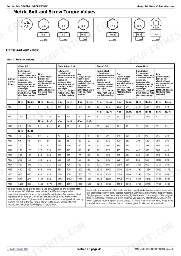
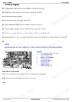
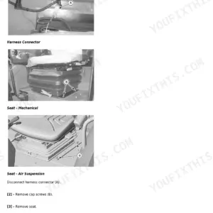
This 709-page John Deere 5085E, 5090E, 5090EL, 5100E and 5100E (FT4) Repair Manual (OEM #TM134519) puts the complete factory teardown for every group, from Engine and Electrical through Hydraulics and Cab, in your hands. Open it and you get hydraulic pump, cooler, and selective control valve schematics, a full torque values section covering metric and Unified Inch bolts, and step-by-step procedures running from Group 05 Safety all the way to Special Tools and dealer-fabricated fixtures. Set your clutch enable solenoid cap screw to 22 to 28 N-m, and torque the transmission forward solenoid valve to 14.2 N-m before you close the housing back up. No more flipping between a parts catalog and a forum thread trying to guess what your 5100E actually needs. This PDF carries a searchable text layer and bookmarks, so you jump straight to Drive Systems, Steering and Brakes, or any of the nine major systems without hunting through 700 pages by hand.
What's Inside This John Deere 5085E to 5100E Series Repair Manual
| System | Pages | Key Topics |
|---|---|---|
| General Information | 7-87 | Safety, General Specifications, Fuel and Lubricants, Serial Number Locations |
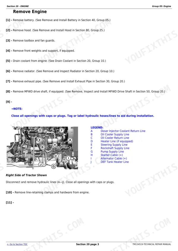
| Engine | 88-117 | Cooling System |
| Fuel, Air Intake, Exhaust, and Cooling | 118-155 | Fuel System, Air Intake System, Air Exhaust System |
| Electrical | 156-346 | Battery, Starter and Alternator, Electrical System Components, Wiring Harnesses |
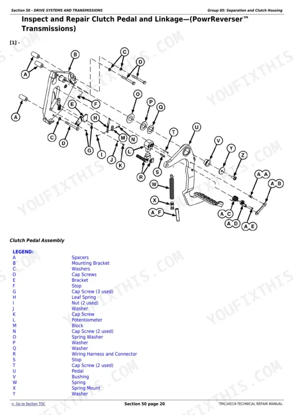
| Drive Systems and Transmissions | 347-381 | Separation and Clutch Housing, Pr Transmission, Clutch Assembly, Differential, Final Drives, Rear PTO |
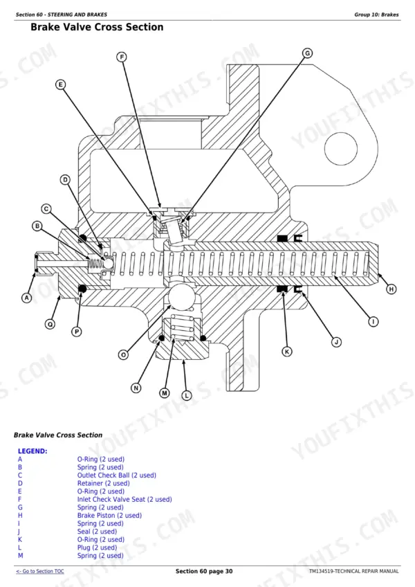
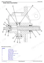
| Steering and Brakes | 382-425 | Steering, Brakes |
| Hydraulics | 426-549 | Hydraulic Pump and Filter, Hydraulic Oil Cooler, Rockshaft, Rear Selective Control Valve, Mid-Mount Selective Control Valve |
| Miscellaneous | 550-576 | 3-Point Hitch, Fenders, Hood |
| Cab/Open Operator Station | 577-706 | Seat and Support, Control Console and Panel, Roll-Gard, Cab Components, Air Conditioning System, Heating System |
| Special Tools | 707-709 | Dealer Fabricated Tools (Final Drive Turning Tool, Compressor Holding Fixture, Snap Ring Removal Tool) |
Documents This Manual Refers To
The manufacturer cites these publications by number. We carry them:
Quick Reference Specifications
| Specification | Value | Page |
|---|---|---|
| All Models | ||
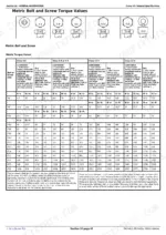
| Metric Bolt and Screw Torque Values | 45 | p. 6 |
| Unified Inch Bolt and Screw Torque Values | 46 | p. 6 |
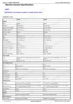
| Clutch Enable Solenoid Cap Screw | 22–28 N·m (16–21 lb.-ft.) | p. 158 |
| Transmission Forward (Low) Solenoid | 14.2 N·m (125 lb.-in.) | p. 158 |
| Replacement of Engine Control Unit (ECU) | Perform Programming Control Units in Section 245, Group 05B | p. 209 |
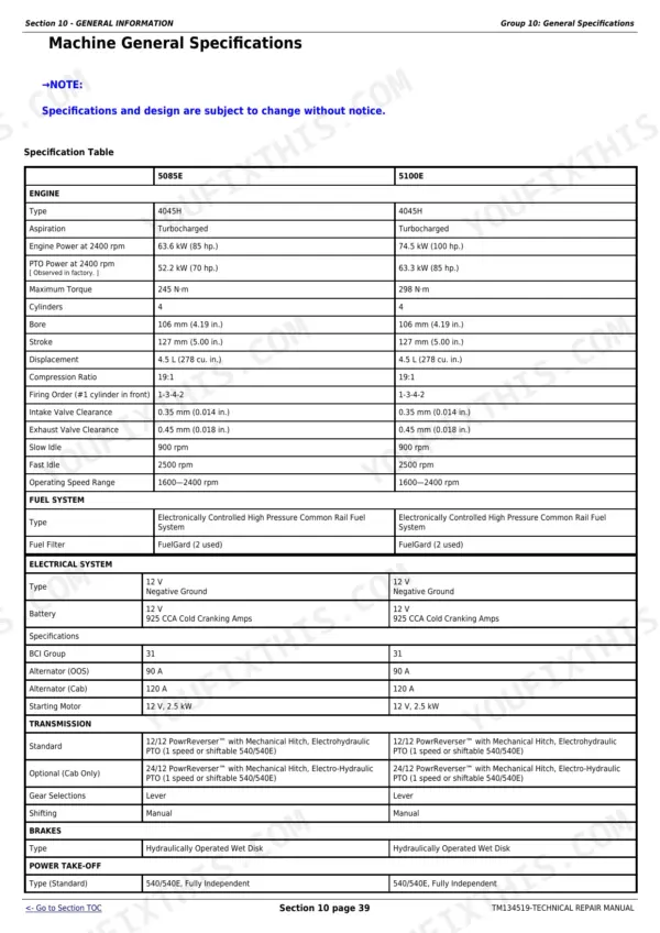
| Fuel Tank Capacity | 115 L (30 U.S. gal) | p. 47 |
| Cooling System Capacity | 11.4 L (3 U.S. gal) | p. 47 |
| Crankcase (including filter) Capacity | 12.1 L (3.2 U.S. gal) | p. 47 |
| Transmission and Hydraulic System Capacity | 43.5 L (11.5 gal) | p. 47 |
| Engine Lifting Strap Cap Screw Torque | 125 N·m (92 lb.-ft.) | p. 88 |
| 5085E | ||
| Engine Power at 2400 rpm, 5085E | 63.6 kW (85 hp.) | p. 45 |
| 5100E | ||
| Engine Power at 2400 rpm, 5100E | 74.5 kW (100 hp.) | p. 45 |
John Deere 5085E to 5100E Series Common Problems This Manual Covers
John Deere 5085E engine cranks but won't start, throwing an injector supply voltage fault code
Inspect wiring and connectors feeding Injectors 1 and 4 for corrosion or chafing near the cylinder head, and test supply voltage at each connector with the key on. Torque any disturbed bracket hardware to 13-17 N·m (115-150 lb.-in.) per page 158. If the ECU is faulty, replace it and follow the programming steps in Section 245, Group 05B on page 209.
Manual Section: Electrical System Component Replacement p. 209Engine loses power or shuts off completely when exhaust gas temperature reads abnormally high
Check the EGR valve position sensor signal against the ECU diagnostic reading; a signal reading too high points to a sticking valve or carbon buildup in the cooler. Clean the EGR cooler passages and valve bore, then inspect the exhaust piping for restriction. Torque the turbocharger mounting flange nuts to 80 N·m (59 lb.-ft.) per the specs on page 139 during reassembly.
Manual Section: Fuel, Air Intake, Exhaust, and Cooling p. 139Clutch pedal fails to engage transmission gears, tractor won't shift out of neutral
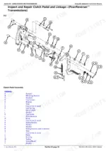
Check the clutch pedal sensor signal at the Main Control Module with the diagnostic display; an out-of-range reading blocks gear engagement entirely. Inspect the sensor linkage for wear or a loose pivot pin and adjust pedal free travel. If you separate the clutch housing from the engine, torque the M20 housing cap screws to 430 N·m (317 lb.-ft.) as listed on page 347.
Manual Section: Transmission and Clutch Repair p. 347Central Control Module throws a stored configuration data error after battery disconnect or reset
Cycle the key and watch for fault code 000628.02 to clear; if it persists, reseat the CCU connector and check for corrosion at the battery ground strap. Torque the CCU mounting hardware to 13-17 N·m (115-150 lb.-in.) per page 158. If configuration data won't reload, reprogram the control unit following the procedure in Section 245, Group 05B on page 209.
Manual Section: Electrical System Component Replacement p. 209Injector number 2 calibration code error triggers rough idle and inconsistent fuel delivery
Pull the injector calibration codes with the diagnostic tool and compare Injector 2's stored code against the code stamped on the injector body; a mismatch throws error 000652.13. Replace the injector if the code can't be re-entered, then reprogram the ECU. Check fuel supply pressure and lines per the fuel system procedures starting on page 118, and confirm the 115 L (30 U.S. gal) tank isn't contaminated.
Manual Section: Fuel System Service and Component Replacement p. 118Frequently Asked Questions
What are the torque specs for John Deere 5090EL flywheel bolts?
The torque specification for the clutch-to-flywheel cap screws is 36 N·m (27 lb-ft). This information is found in the engine specifications under Group 05 - Engine. p. 88
What are the replacement specifications for Clutch Pedal Sensor?
The manual describes the procedure to remove and install the clutch pedal position sensor, which involves removing two screws. However, specific functional replacement specifications for the sensor itself (e.g., resistance values or part numbers) are not provided in this manual. p. 216
What are the recommended engine oil and filter service intervals for Interim Tier 4, Final Tier 4, Stage IIIB, and Stage IV engines when using John Deere Plus-50 II oil?
When using John Deere Plus-50 II oil and diesel fuel with sulfur content less than 15 mg/kg (15 ppm), the extended oil and filter change interval is 500 hours. If other approved oils are used, the interval is 250 hours, which may be extended with oil analysis. p. 71
What is the fuel tank capacity for the 5085E and 5100E tractors?
The fuel tank capacity for both 5085E and 5100E tractors is 115 L (30 U.S. gal). This applies to both Cab and Open Operator Station models. p. 47
How quickly can I access this John Deere 5085E & variants manual after buying?
You get a 709-page searchable PDF that downloads instantly after checkout. Open it on your laptop, tablet, or phone, and bring it right to the shop floor.
Can I print pages of this John Deere 5085E & variants manual for my own shop?
Yes. Many mechanics print the section they need for their own shop and bring it to the bench.
Does this John Deere 5085E & variants manual include hydraulic schematics?
Included. Hydraulic system schematics cover all circuits, control valves, and component specifications for the John Deere 5085E & variants.






Reviews
There are no reviews yet.