
Part of the John Deere Repair Manuals.
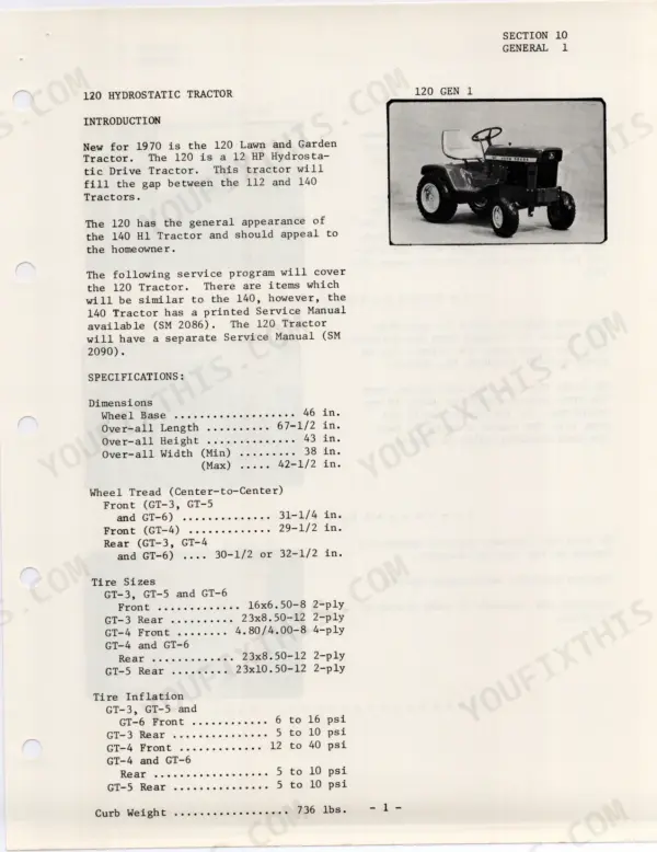
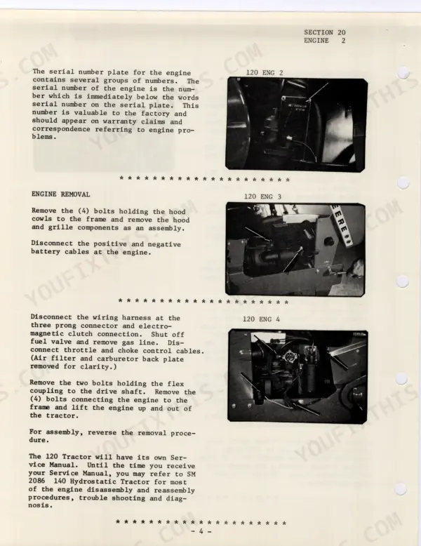
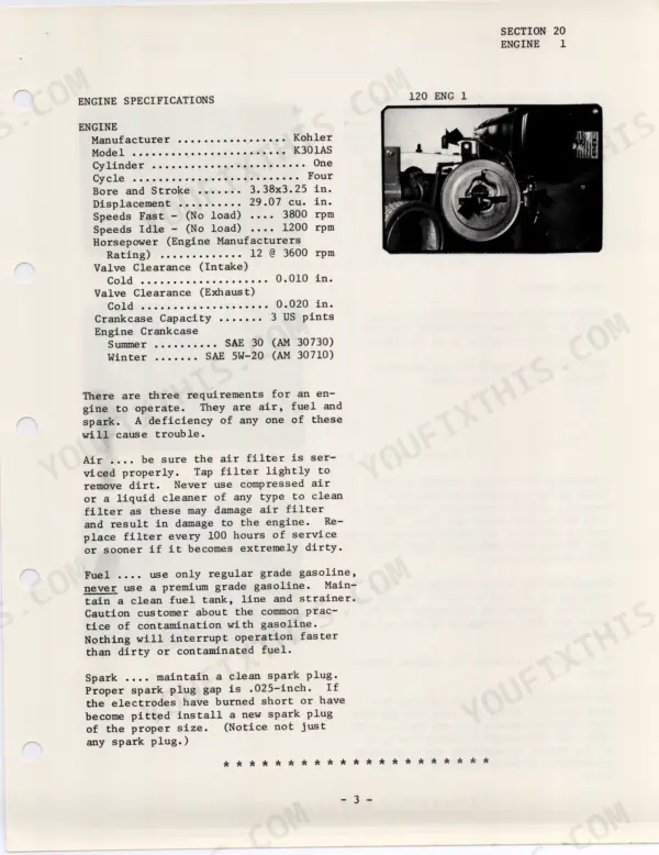
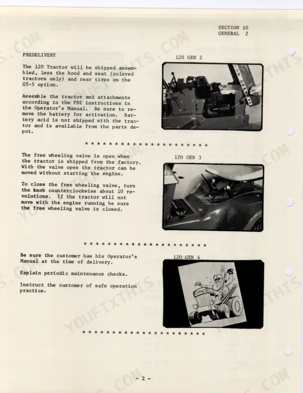
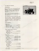
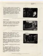
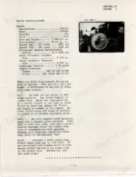
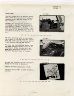
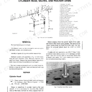
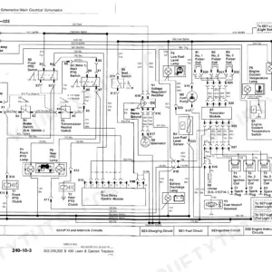
Wrenching on a 1970-model 120? This 54-page John Deere 120 service manual PDF covers the hydrostatic tractor from carburetor to differential. Inside: wiring diagrams for the charging and ignition circuits, hydraulic schematics tracing the gerotor charge pump, check valves, and implement relief valve, plus full hydrostatic drive teardown steps covering swashplates, valve plates, and cylinder blocks. You also get brake, axle, and differential procedures right down to ring gear pattern checks and backlash adjustment with a dial indicator. Torque the charge pump housing cap screws to 50-55 ft. lbs. and set the spark plug gap at 0.025 inch; those are factory numbers, not forum guesses. Your tractor is down and the clock is ticking. Bookmarked sections and a real text layer let you search any spec and get back to wrenching.
What's Inside This John Deere 120 Manual
| System | Pages | Key Topics |
|---|---|---|
| General | 3-4 | Introduction, Specifications, Predelivery |
| Engine | 5-7 | Throttle Cable Adjustment, Governor Adjustment, Tachometer Usage |
| Fuel System | 8-9 | Idle Mixture Adjustment, Idle Stop Screw Adjustment, Carburetor Service |
| Electrical System | 10-21 | Meter Polarity Adjustment, Ampere Reading, Charging System Service |
| Specifications | 22 | Dimensions, Wheel Tread, Tire Sizes, Engine Specifications, Transmission |
| Driveshaft Servicing | 22-23 | Roll Pins, Drive Shaft Yokes, Flexible Disk, Clutch Cone, Engine Mounting Bolts |
| Hydrostatic Drive | 24-38 | Piston Operation, Hydrostatic Drive Pistons, Swashplate Operation, Operation of Hydrostatic, Reversing in Variable Pump Circuits, Circuit Diagram, Hydrostatic Removal, Testing and Disassembly, Charge Pump Service, Implement Relief Valve, Check Valves, Hydrostatic Disassembly, Center Section Housing Removal, Valve Plate Inspection, Valve Plate Cleaning, Center Section Needle Bearings, Cylinder Block Removal, Piston Cleaning, Piston Inspection, Slipper Retainer Inspection, Cylinder Block Disassembly, Motor Swash Plate Removal, Transmission Motor Shaft Removal, Motor Shaft Bearing Extension, Trunnion Shaft Assembly Removal, Thrust Plate Inspection, Trunnion Bearing Installation, Pump Shaft Seal Installation, Reassembly Procedures, Piston Assembly Handling |
| Brake Service | 39-40 | Seal Retainer Centering, Brake Shoe Inspection, Brake Drum Installation |
| Axle Shaft, Seal and Bearing Service | 41 | Axle Shaft, Seal or Bearing Service |
| Differential and Final Drive | 42-52 | Differential Removal, Differential Disassembly, Pinion Shaft Removal, Pinion Gear Removal, Ring Gear Replacement, Thrust Washer Installation, Pinion Gear Alignment, Pinion Shaft Installation, Differential Bearing Removal, Bearing Installation, Spur Gear Removal, Pinion Assembly Removal, Pinion and Spur Gear Assembly, Outer Bearing Race Replacement, Inner Bearing Race Replacement, Assembling Pinion and Differential Group, Pinion and Spur Gear Installation, Outer Bearing Pressing, Differential Assembly Installation, Ring Gear Pattern Check, Desirable Pattern, Toe Pattern, Backlash Check, Welch Plug Installation, Rear Housing Installation, Hydraulic |
Quick Reference Specifications
| Specification | Value | Page |
|---|---|---|
| Battery capacity | 40 amp-hr. | p. 10 |
| Spark plug gap | 0.025 in. | p. 10 |
| Spark plug torque | 15 to 20 ft. lbs. | p. 17 |
| Charge relief valve plug torque | 15-17 ft. lbs. | p. 28 |
| Charge pump housing cap screws torque | 50-55 ft. lbs. | p. 29 |
| Charge pressure | 75-110 PSI | p. 27 |
| Implement relief valve pressure | 500-550 PSI | p. 29 |
| Wheel Base | 46 in. | p. 3 |
| Curb Weight | 736 lbs. | p. 3 |
| Engine Crankcase Capacity | 3 US pints | p. 5 |
| Fuel Tank Capacity | 1.75 US Gallons | p. 8 |
| Breaker Point Gap | 0.020 in. | p. 10 |
John Deere 120 Common Problems This Manual Covers
John Deere 120 hydrostatic drive loses power going uphill after warming up, tractor slows then stops moving
Check charge pressure first before condemning the pump. Connect a gauge at the charge pump relief valve using the test procedure on page 29, then run the engine at operating speed. Correct charge pressure is 75-110 PSI. Low readings point to a worn charge pump or stuck relief valve; inspect the rotor assembly before splitting the unit.
Manual Section: Hydrostatic Drive Troubleshooting p. 29Weak reverse or no reverse at all when backing up a slope or pulling a load
Test the check valves in the center section; a leaking check valve bleeds off reverse-side pressure first. Remove the plungers following page 32 and inspect each O-ring and back-up washer for nicks. Verify charge pressure holds 75-110 PSI in both directions. Replace worn plungers and renew all O-rings on reassembly.
Manual Section: Check Valves p. 32Loud whining or grinding noise from the rear transaxle, gets worse as the oil heats up
Drain the transmission oil and cut open the filter; metal flake means internal wear, foam means the pump is sucking air. Inspect the valve plates for scoring and erosion using the procedure on page 33. On reassembly, torque the center section housing bolts 33-37 ft. lbs. and bleed the unit before loading it.
Manual Section: Valve Plate Inspection p. 33Engine runs fine but tractor suddenly stops moving in both forward and reverse
Check the free wheeling control first; if the bypass lever got knocked open the unit cannot build pressure. Next pull the fender deck assembly per page 28 and inspect the driveshaft roll pins and flex coupling for sheared pins. If both check out, gauge the charge circuit; anything below 75 PSI means charge pump trouble.
Manual Section: Hydrostatic Removal p. 28Hydraulic lift raises the mower deck slowly or will not hold it up
Attach a pressure gauge to the front implement outlets and cycle the lift; proper implement pressure is 500-550 PSI per the test on page 29. Low pressure means a weak relief spring or scored cone. Remove the relief valve plug, inspect the spring and cone, and torque the plug 15-17 ft. lbs. with a new O-ring.
Manual Section: Implement Relief Valve p. 31Frequently Asked Questions
What is the engine crankcase oil capacity for the John Deere 120?
The engine crankcase capacity for the John Deere 120 is 3 US pints. For summer operation, use SAE 30 (AM 30730) oil, and for winter operation, use SAE 5W-20 (AM 30710) oil. p. 5
What is the correct spark plug gap for the John Deere 120?
The proper spark plug gap for the John Deere 120 is 0.025-inch. It should be inspected and regapped every 100 hours. p. 17
What is the transmission oil capacity and recommended lubricant for the hydrostatic transmission?
The transmission oil reservoir capacity is 5 US quarts. The recommended lubricant is John Deere Type 303 Special-Purpose (R34690R) or Automatic Transmission Fluid Type A. p. 22
What is the specified valve clearance for the engine?
The intake valve clearance is 0.010 inch (cold) and the exhaust valve clearance is 0.020 inch (cold). p. 5
What is the correct charge pressure for the hydrostatic transmission?
The correct charge pressure for the hydrostatic transmission is 75 to 110 PSI. This can be checked by tapping into the center section and connecting a pressure gauge while the unit is in neutral. p. 29
Is this John Deere 120 manual a download or a disc?
This is a 54-page searchable PDF ready for immediate download. Works on any device, so pull it up on your phone while you're under the hood. No shipping, no waiting.
Can I print just the pages I need from this John Deere 120 manual?
Yes. Print the pages you need for the job in your own shop, and bin them when they get greasy.








Reviews
There are no reviews yet.