
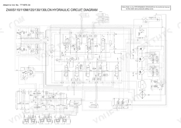
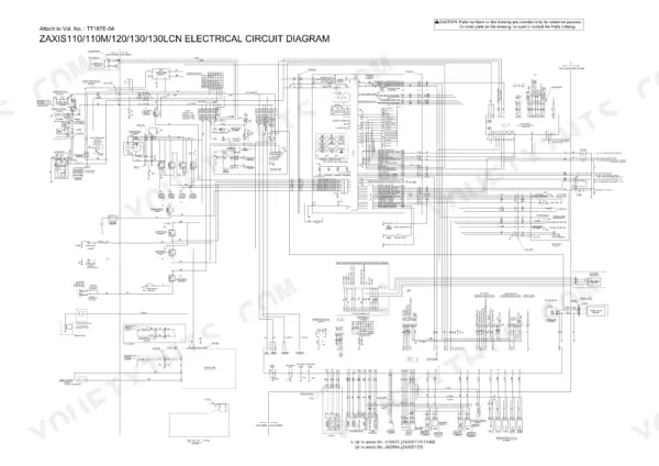
Part of the Hitachi Repair Manuals.
This is the full Hitachi service set for the Zaxis 110, 110M, 120, 130, 130LCN and the short tail 125US, 135US and 135UR: the Technical Manual for operational principle (TO187E), the Troubleshooting volume (TT187E), the Workshop Manual (W187E) under publication KM-187E, plus the fold out electrical and hydraulic circuit sheets printed per model and the supplementary technical set for the 110, 120, 125US and 135US. You get the theory (HIOS pump control, pilot circuit, signal control valve), the numbers (relief pressures, drainage limits, torques), the test procedures to prove a component bad before you pull it, and the teardown steps for pumps, motors, the swing device and the entire undercarriage. Written for the Isuzu 4BG1 powered machines, with model specific spec tables throughout.
What's Inside This Hitachi Zaxis 110–135 Repair Manual
| System | Pages | Key Topics |
|---|---|---|
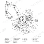
| Technical Manual: General | 1-58 | Machine Model Designations, Component Layout, Serial Number Locations, Standard Maintenance Intervals, Dimensions Against the Earlier EX Series |
| Technical Manual: System | 59-176 | Hydraulic System Layout, Pilot Circuit, Pump Control, HIOS Controller Behaviour, Electrical System Architecture, Engine Control |
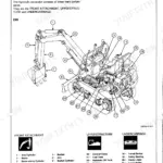
| Technical Manual: Component Operation | 177-318 | Main Pump, Pilot Valve, Control Valve, Swing Device, Travel Device, Signal Control Valve, Solenoid Valve Unit |
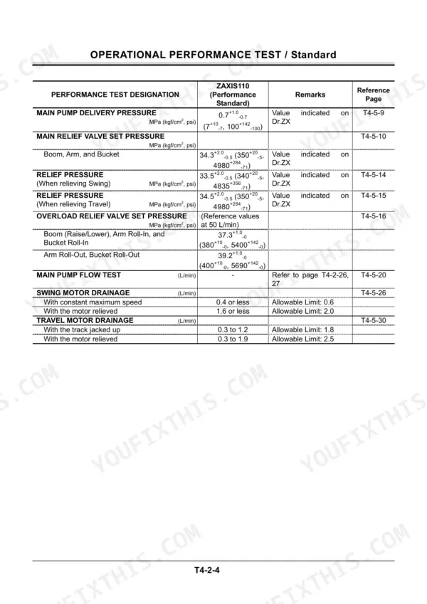
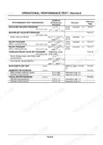
| Operational Performance Test | 319-503 | Test Standards, Engine Test, Excavator Test, Component Test, Adjustment Procedures |
| Troubleshooting | 504-773 | Component Layout, Fault Diagnosis Flowcharts a to D, Electrical System Inspection, ICX Diagnostics |
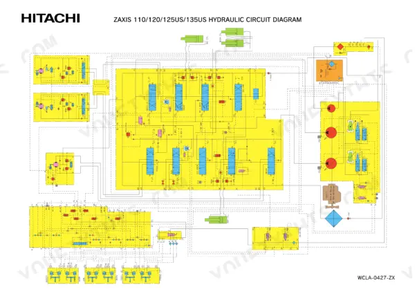
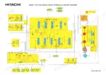
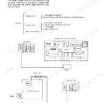
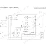
| Attached Circuit Diagrams | 774-824 | Electrical Circuit Diagrams per Model, Connector Charts, Cab Harness, Engine Harness, Monitor Harness, Hydraulic Circuit Diagrams, Quick Hitch and Overload Alarm Sheets |
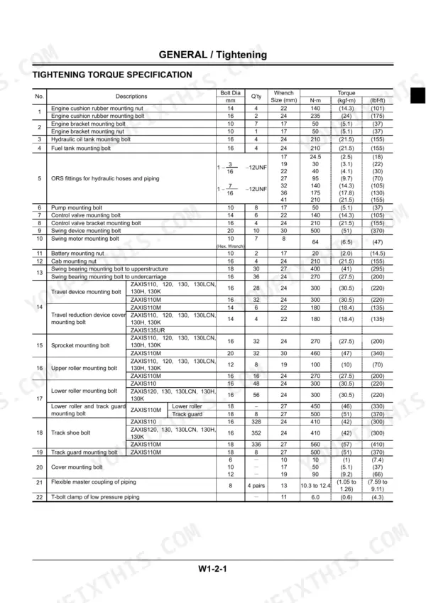
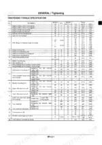
| Workshop Manual: General | 825-888 | Precautions for Disassembling and Assembling, Tightening Torque Specifications, Torque Chart, Piping Joint Standards |
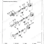
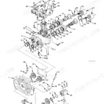
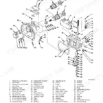
| Workshop Manual: Upperstructure | 889-1140 | Swing Device, Main Pump, Control Valve, Pilot Valve, Swing Motor, Cab and Covers Removal and Installation |
| Workshop Manual: Undercarriage | 1141-1268 | Travel Device, Centre Joint, Track Adjuster, Idler, Track Roller, Sprocket, Track Chain |
| Workshop Manual: Front Attachment | 1269-1344 | Boom, Arm, Bucket, Cylinders, Bushings and Pins, Front Joint Disassembly |
| Workshop Manual: Engine and Accessory | 1345-1572 | Engine Removal and Installation, Cooling Package, Fuel System, Air Conditioner, Accessory Drive |
| Supplementary Technical Manual (110, 120, 125US, 135US): General | 1573-1612 | Component Layout for the Supplemented Machines, Serial Coverage, Specification Tables |
| Supplementary Technical Manual (110, 120, 125US, 135US): System | 1613-1692 | Pump Delivery and Pilot Circuit Routing, Signal Control Valve Behaviour, Solenoid Valve Unit, Monitor Inputs |
| Supplementary Technical Manual (110, 120, 125US, 135US): Component Operation | 1693-1789 | Pump, Valve and Motor Operation for the Supplemented Machines |
| Supplementary Performance Check (110, 120, 125US, 135US) | 1790-1905 | Performance Check Safety, Test Standards, Engine and Excavator Tests |
| Supplementary Troubleshooting (110, 120, 125US, 135US) | 1906-2121 | Adjustment Data List, Sensor Activating Ranges, Connector Charts, Fault Diagnosis Flowcharts |
Quick Reference Specifications
| Specification | Value | Page |
|---|---|---|
| Main relief valve set pressure - boom, arm, bucket | 34.3 MPa (350 kgf/cm2, 4980 psi), tolerance +2.0 / -0.5 | p. 363 |
| Relief pressure when relieving swing | 33.5 MPa (340 kgf/cm2, 4835 psi), tolerance +2.0 / -0.5 | p. 363 |
| Relief pressure when relieving travel | 34.5 MPa (350 kgf/cm2, 4980 psi), tolerance +2.0 / -0.5 | p. 363 |
| Overload relief - boom, arm roll-in, bucket roll-in | 37.3 MPa (380 kgf/cm2, 5400 psi), tolerance +1.0 / -0 | p. 363 |
| Overload relief - arm roll-out, bucket roll-out | 39.2 MPa (400 kgf/cm2, 5690 psi), tolerance +1.0 / -0 | p. 363 |
| Primary pilot pressure at fast idle | 4.0 MPa (40 kgf/cm2, 570 psi), tolerance +1.0 / -0.5 | p. 362 |
| Secondary pilot pressure | 3.4 to 4.0 MPa (34 to 40 kgf/cm2, 483 to 570 psi) | p. 362 |
| Main pump maximum flow, theoretical | 100 L/min (26.4 US gpm) x 2 | p. 43 |
| Swing motor drainage at constant maximum speed | 0.4 L/min or less | p. 363 |
| Swing motor drainage with the motor relieved | 1.6 L/min or less | p. 363 |
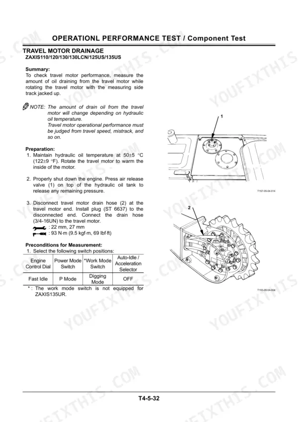
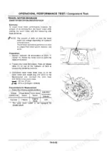
| Travel motor drainage with the track jacked up | 0.3 to 1.2 L/min | p. 363 |
| Travel motor drainage with the motor relieved | 0.3 to 1.9 L/min | p. 363 |
| Slow idle speed | 1000 +/- 100 min-1 | p. 360 |
| Fast idle speed, normal | 1915 +/- 50 min-1 | p. 360 |
| Engine compression pressure after warm-up | 2.95 MPa (30.0 kgf/cm2, 427 psi) | p. 360 |
| Valve clearance, inlet and exhaust | 0.4 mm | p. 360 |
| Nozzle injection pressure | 18.1 MPa (185 kgf/cm2, 2630 psi) | p. 360 |
| Hydraulic oil temperature for measurement | 50 +/- 5 C (122 +/- 9 F) | p. 457 |
| Swing device mounting bolt torque | 500 N.m (51 kgf.m, 370 lbf.ft) | p. 873 |
| Track shoe bolt torque | 410 N.m (42 kgf.m, 300 lbf.ft) | p. 873 |
Hitachi Zaxis 110–135 Common Problems This Manual Covers
Machine feels weak in the dig, cycle times have slowed, operator blames the pump
Run the Operational Performance Test before spending money. Check main relief at 34.3 MPa with a tolerance of +2.0/-0.5 with oil at 50 +/- 5 C, then compare cylinder speeds against the per model tables. The Component Test procedures separate a tired pump from a relief valve set low.
Manual Section: Operational Performance Test p. 356Swing is sluggish or the upperstructure drifts on a slope with the lever centred
Measure swing motor drainage per the performance section: 0.4 L/min or less at constant maximum speed, 1.6 L/min or less relieved. Over those limits, the Workshop Manual Upperstructure section covers swing motor and swing device teardown, and the reduction gear mounting bolts torque to 500 N.m on reassembly.
Manual Section: Workshop Manual: Upperstructure - Swing Device p. 363Machine pulls to one side when travelling straight, or one track is noticeably slower
Jack the slow side and run the travel motor drainage check: 0.3 to 1.2 L/min jacked up, 0.3 to 1.9 L/min relieved. If drainage passes, the Troubleshooting flowcharts point you toward the centre joint seals or the travel spool in the control valve instead of the motor.
Manual Section: Troubleshooting - Fault Diagnosis Flowcharts p. 485Engine starts hard, smokes and lacks power at working rpm
The engine test procedure gives you the baselines: compression of 2.95 MPa warm, valve clearance of 0.4 mm, nozzle pop pressure of 18.1 MPa, slow idle at 1000 +/- 100 min-1 checked against your model's table. The Engine and Accessory section then covers fuel system service and injector access.
Manual Section: Workshop Manual: Engine and Accessory p. 1345Frequently Asked Questions
The monitor is showing a fault and the machine has derated. Does this manual actually cover the electronics, or is it just wrenching?
It covers the electronics properly. The Troubleshooting volume (TT187E) walks the fault diagnosis flowcharts A to D, explains what the ICX diagnostics can read out through the monitor, and gives step by step electrical inspection with connector charts so you can check the actual harness pins. The System section explains how the HIOS controller decides pump output, which is what you need to understand before blaming a sensor. The circuit sheets are printed per model, so pull the diagram for your exact machine. p. 504
I want to check hydraulic pressures before condemning the main pump. Are the test specs in here?
Yes, the Operational Performance Test section has the full standards. Main relief for boom, arm and bucket is 34.3 MPa (350 kgf/cm2, 4980 psi) with a tolerance of +2.0/-0.5, swing relieves at 33.5 MPa with a tolerance of +2.0/-0.5, and the overload reliefs run 37.3 to 39.2 MPa depending on the circuit, each with a tolerance of +1.0/-0. It also tells you to test with hydraulic oil at 50 +/- 5 C, because cold oil numbers will lie to you. Adjustment procedures are included, not just the targets. p. 363
Are the specs the same across all these models, or do I need to watch which machine I have?
Watch your model. The spec tables are printed per machine and the differences are real: the 110 and 110M carry different travel speed standards (6.5 versus 8.7 seconds per 10 m in the travel test), and the short tail 125US, 135US and 135UR have their own idle speed figures. The supplementary technical set adds coverage for later serial 110, 120, 125US and 135US machines. Always read the column for your model and serial range before adjusting anything. p. 360
Does it cover full teardown of the travel motors and the track gear, or just removal?
Full teardown. The Workshop Manual Undercarriage section covers the travel device, centre joint, track adjuster, idler, track rollers, sprocket and track chain with disassembly, inspection and assembly steps. Before you pull a travel motor, run the drainage test in the performance section: 0.3 to 1.2 L/min with the track jacked up is normal, so a motor inside that band is not your problem. Track shoe bolts go back on at 410 N.m (42 kgf.m, 300 lbf.ft). p. 1141
Is the engine side covered, or do I need a separate Isuzu manual?
The service set covers what an excavator mechanic needs on the BB-4BG1TRG: compression standard of 2.95 MPa after warm up, valve clearance of 0.4 mm inlet and exhaust, nozzle injection pressure of 18.1 MPa, plus engine removal and installation, the cooling package, fuel system and accessory drive in the Workshop Manual Engine and Accessory section. Engine speed test standards are in the performance section, printed per model. For a full crank out rebuild of the Isuzu block you would still want the engine maker's internals manual. p. 360
Reviews
There are no reviews yet.