
Part of the Hitachi Repair Manuals.
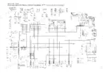
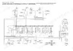
This 655-page Hitachi Zaxis 40U/50U Technical Manual (OEM #T1LDE-00) covers the full Zaxis 40U and 50U hydraulic excavator line, technical and workshop sections included. You get wiring diagrams for the power circuit, indicator light and accessory circuits, and preheating, starting, and charging circuits, plus hydraulic schematics covering the solenoid valve unit and pump control system. Inside: a full troubleshooting section, torque specification tables, exploded parts views, and maintenance interval schedules pulled straight from the factory workshop manual. The pilot filter spec calls for 10 μm filtration, and the solenoid valve unit's relief set pressure runs 3.9 MPa (40 kgf/cm², 570 psi), real numbers, not shop-forum guesses. No more chasing a hydraulic fault with a test light and a hunch. This PDF carries a full bookmark structure and a searchable text layer, so you can jump straight to the wiring or hydraulic section, find your spec, and get back under the machine.
What's Inside This Hitachi Zaxis 40U, 50U Manual
| System | Pages | Key Topics |
|---|---|---|
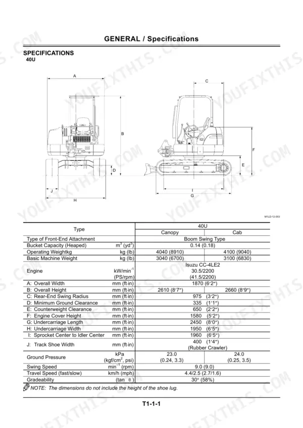
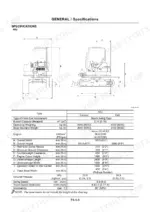
| General & Machine Specifications (Technical) | 32-49 | Machine Dimensions and Weight, Engine Specifications, Hydraulic Component Specifications, Performance Data |
| System Operation | 50-77 | Hydraulic System, Control System, Electrical System, Power Circuit Operation Overview |
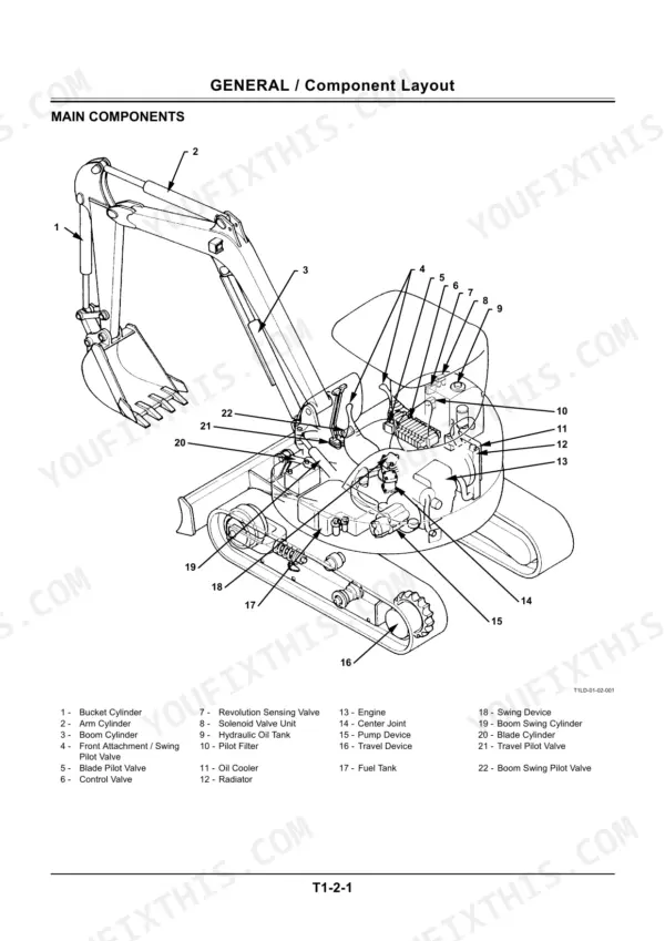
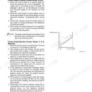
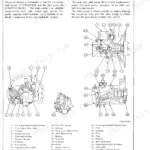
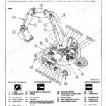
| Component Operation | 78-159 | Main Pump, Control Valve, Pilot Valve, Solenoid Valve Unit, Swing Motor, Travel Motor, Cylinders |
| Operational Performance Test | 160-209 | Pump Delivery Pressure, Relief Set Pressure, Engine Speed, Cylinder Cycle Time, Track Adjuster Valve |
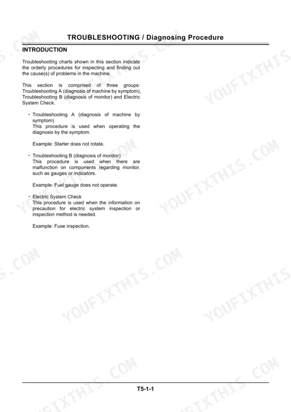
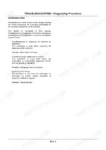
| Troubleshooting (Technical) | 210-261 | Diagnostic Procedures, Electrical System Inspection, Fault Symptom Charts, Fuse and Circuit Checks |
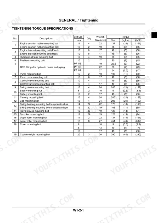
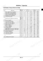
| General Information (Workshop) | 293-316 | Tightening Torques, Ors Fitting Torques, Service Standards, Sealant Application |
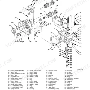
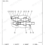
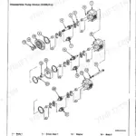
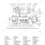
| Upperstructure | 317-420 | Swing Device, Pump Device, Control Valve, Pilot Valve, Cab and Counterweight Removal and Installation |
| Undercarriage | 421-478 | Travel Device, Center Joint, Track Adjuster, Track Shoe, Roller and Idler Removal and Assembly |
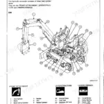
| Front Attachment | 479-534 | Boom, Arm, Bucket, Hydraulic Cylinders Removal, Installation and Disassembly |
| Engine | 535-610 | Engine Removal and Installation, Cylinder Head, Timing, Fuel Injection, Disassembly and Assembly |
| Lubricating System | 611-614 | Oil Pump, Oil Filter, Lubrication Circuit |
| Cooling System | 615-632 | Radiator, Water Pump, Thermostat, Coolant Specifications |
| Troubleshooting (Workshop) | 633-650 | Engine Fault Diagnosis, Hydraulic Fault Diagnosis, Repair Procedures |
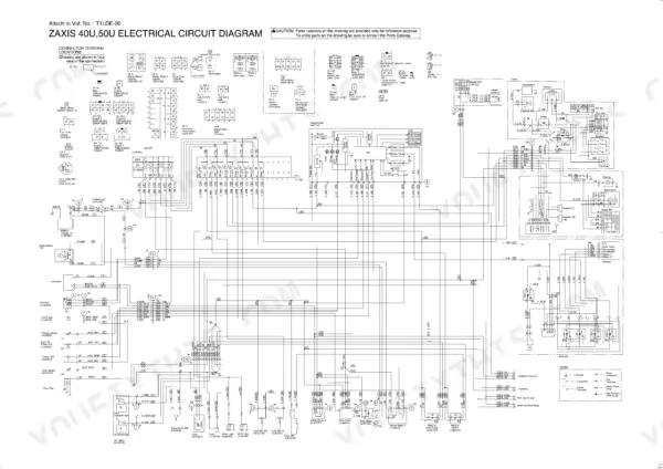
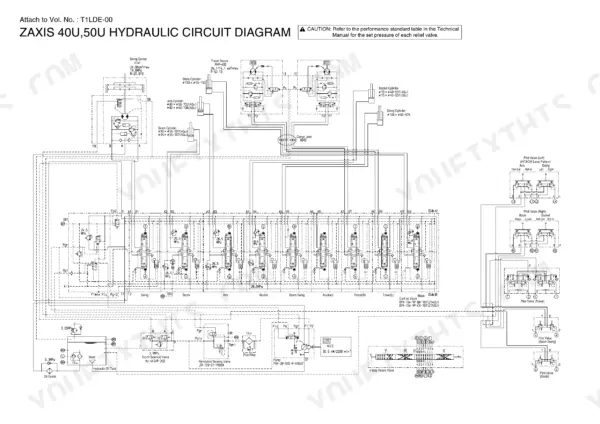
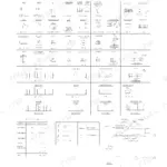
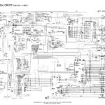
| Circuit Diagrams (Fold-Out Schematics) | 651-655 | Electrical (Elc) Circuit, Engine Wiring, Floor Harness, Hydraulic Circuit, Main Harness |
Quick Reference Specifications
| Specification | Value | Page |
|---|---|---|
| Pilot Filter | 10 μm | p. 49 |
| Solenoid valve unit relief set pressure | 3.9 MPa (40 kgf/cm², 570 psi) | p. 48 |
| Track Adjuster Valve | 1 to 1.5 turns counterclockwise | p. 159 |
| Unload valve lock-nut torque | 34 to 39 N·m (3.5 to 4 kgf·m, 25 to 29 lbf·ft) | p. 208 |
| Coolant temperature for overheat indicator | above 110 ± 2 °C(230 ± 3.6 °F) | p. 249 |
| ORS fitting torque (PF 1/8) | 29.5 N·m (3 kgf·m) (22 lbf·ft) | p. 303 |
Hitachi Zaxis 40U, 50U Common Problems This Manual Covers
Hitachi Zaxis 40u engine overheating with coolant temperature warning light staying on
Check the overheat indicator circuit on page 249; it triggers when coolant temperature exceeds 110 ± 2°C (230 ± 3.6°F) for more than 2 seconds. Inspect the radiator core for debris, check coolant level, and verify fuse #8 (5A) reads 12V on page 220. Replace the thermostat if the gauge climbs before normal operating temp.
Manual Section: Monitor & Indicator Malfunctions p. 249Hydraulic system runs sluggish with slow bucket and arm movement despite normal engine RPM
Check the actuator troubleshooting chart on page 221 and confirm voltage at fuse #1 reads 12V. Test main relief pressure; it should hold at 25.1 ± 1.0 MPa per page 166. If pressure sags below spec, inspect the main pump seals and replace the pilot filter (10 μm element) since a clogged filter starves flow before it reaches the cylinders.
Manual Section: Actuator Operating System Troubleshooting p. 221Auto idle system won't drop engine to low idle or triggers sudden speed increases unexpectedly
Check continuity and voltage draw at the auto idle solenoid connector using the electrical inspection procedures. Verify battery voltage holds at 12 V per page 45. Test the selector switch for sticking contacts and check the acceleration sensor wiring for chafing. Replace the auto idle control valve if the solenoid coil resists closing and the engine won't settle to idle.
Manual Section: Electrical System Inspection p. 45Hydraulic fluid pooling under the machine and leaking around cylinder rod seals
Inspect all ORS fittings and hose connections per the torque spec chart on page 303; PF 3/8 fittings tighten to 39 N·m (4 kgf·m, 29 lbf·ft). Wipe fittings clean, pressurize the circuit per page 285's tighten-before-pressure procedure, and watch for weeping at cylinder rod seals. Replace the seal kit if leakage continues after retorquing.
Manual Section: Torque Specifications p. 303Track tension grease valve seized, won't release grease to loosen track sag
Locate the track adjuster valve and back it off 1 to 1.5 turns counterclockwise per page 159 to release grease pressure. If the valve won't turn, relieve pressure gradually and clean around the fitting before applying penetrating oil. Once loose, torque the flange dust seal bolts to 29.5 N·m (3 kgf·m, 21.5 lbf·ft) per page 457 on reassembly.
Manual Section: Undercarriage p. 159Boom feels loose at the foot pin with visible play during digging cycles
Measure boom foot pin diameter; standard is 50 mm with an allowable wear limit of 49.0 mm per page 486. Check clearance between the frame and nut, which should read 2 to 3 mm on page 484. Torque the boom foot pin to 137 N·m (14 kgf·m, 101 lbf·ft) after replacing worn pins or bushings.
Manual Section: Front Attachment System Troubleshooting p. 486Frequently Asked Questions
What are the torque specifications for the Hitachi ZAXIS 40u boom cylinder pin bolts?
The torque specification for the bolt securing the boom cylinder pin is 137 N·m (14 kgf·m, 101 lbf·ft). This applies to bolt (1) used to secure pin (4) when installing the boom cylinder (2) to the swing post. The required wrench size is 22 mm. p. 494
What are the replacement specifications for the hydraulic filter?
The manual specifies a Pilot Filter with a filtration rating of 10 µm. Other filters mentioned include a Full Flow Filter (Paper Type) and a Suction Filter (80 Mesh). The manual does not provide a specific replacement interval for these filters. p. 49
What are the replacement specifications for track tension seals and grease valve components?
The track adjuster assembly includes several components related to tension and grease, such as Dust Seal (2), Wear Ring (5), U-Ring (6), Retaining Ring (7), O-Ring (10), and Valve (11). The manual lists these parts but does not specify periodic replacement intervals for them. p. 450
What is the engine oil capacity for the ZAXIS 40u/50u?
The lubricant volume in the engine oil pan for the ZAXIS 40u/50u (4LE2 engine model) is approximately 8.4 L (8.9 qts). This is a key specification for proper engine lubrication. p. 540
Is this Hitachi manual a digital?
You get a 655-page searchable PDF that downloads instantly after checkout. Open it on your laptop, tablet, or phone, and bring it right to the shop floor.
Am I able to print pages from this Hitachi manual?
Yes. Print the sections you need to take out to the shop for your own use. Standard letter or A4 paper works.
Can I find wiring schematics in this Hitachi manual?
Yes, an electrical wiring diagram is included to help trace the main circuits.
Reviews
There are no reviews yet.