
Part of the Hitachi Repair Manuals.
Three Hitachi factory books bound into one 1,552-page PDF for the ZAXIS-3 family - ZX110-3, ZX110M-3, ZX120-3, ZX130K-3, ZX130L-3, ZX135US-3, ZX135USK-3 and ZX135USL-3.
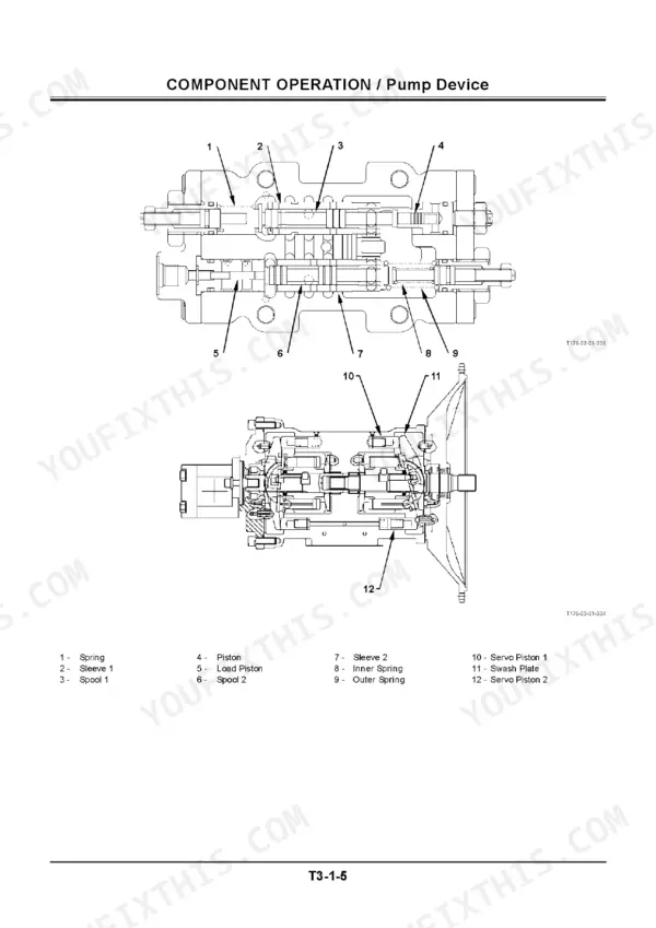
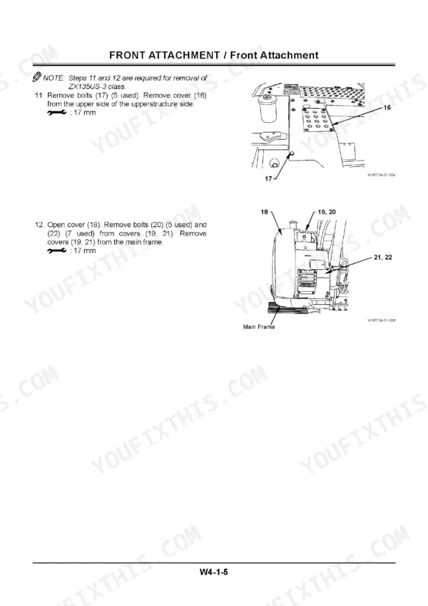
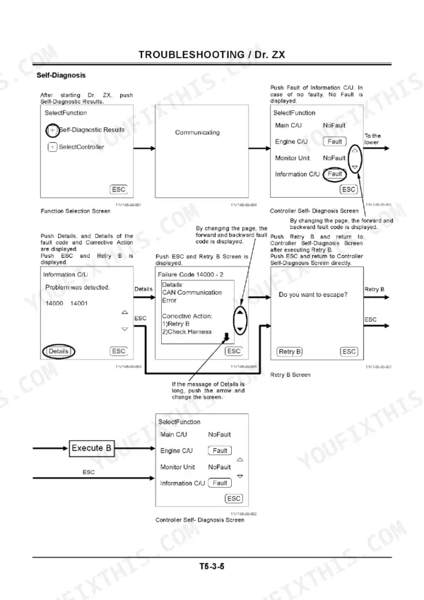
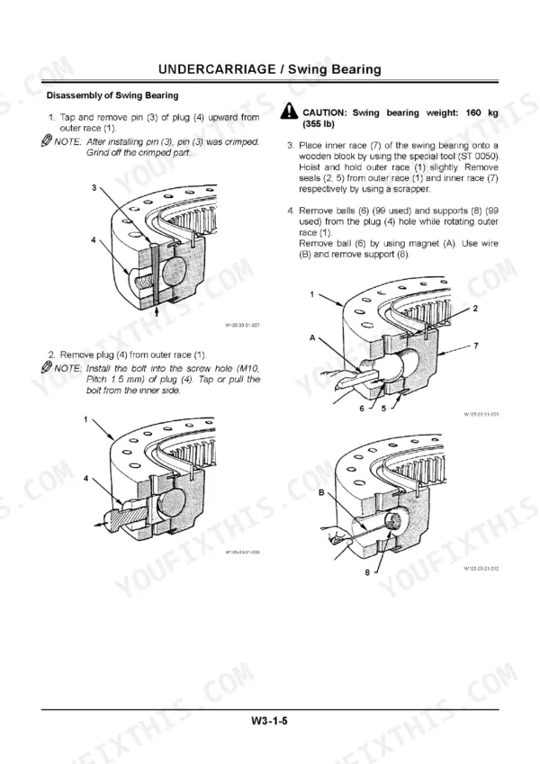
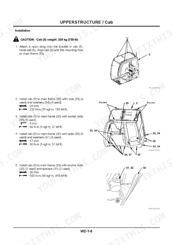
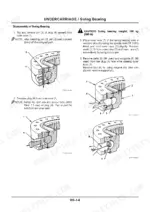
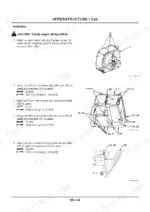
Pages 1-334 are the Technical Manual Operational Principle: specifications, component layout and specifications, then the controller, control system, ECM and hydraulic and electrical systems, component operation for the pump, swing and travel devices and control valve, and the operational performance test. Pages 335-1030 are the Technical Manual Troubleshooting: the diagnosing procedure, the monitor unit, the Dr. ZX dealer tool, E-Shovel, fault codes, Troubleshooting A and B and the electrical system inspection. Pages 1031-1552 are the Workshop Manual: removal, disassembly and assembly for the upperstructure (cab, counterweight, main frame, pilot shut-off), the undercarriage (swing bearing, centre joint, track adjuster, final drive) and the front attachment.
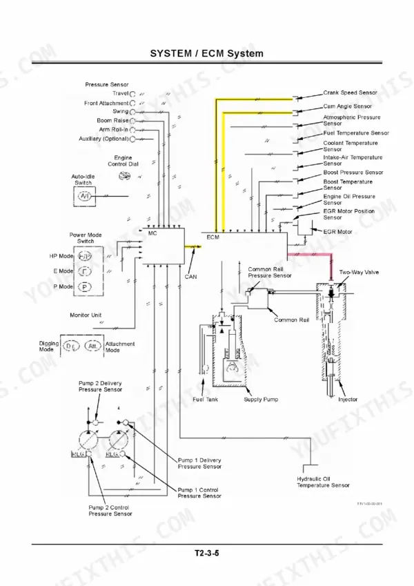
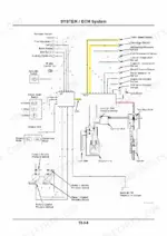
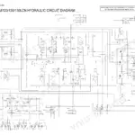
On diagrams, precisely: the control side is illustrated here - page 155 is the ECM system diagram with the main controller, the CAN link, engine sensors, common rail and injector - and the hydraulic section explains the pump control circuits. The full fold-out sheets, however, were attachments to the printed manual: page 1030 lists them (electrical circuit diagram, connector charts, cab, engine, monitor, air-conditioner and switch harness drawings, and the hydraulic circuit diagram including the blade option) and they are not part of this PDF.
What's Inside This Hitachi ZX110-3 - ZX135US-3 Repair Manual
| System | Pages | Key Topics |
|---|---|---|
| General Information and Specifications | 1-46 | Component Layout, Component Specifications |
| Machine Systems - Controller, Control, ECM, Hydraulic and Electrical | 47-224 | Control System, Ecm System, Hydraulic System, Electrical System |
| Component Operation | 225-378 | Pump Device, Swing Device, Control Valve, Pilot Valve, Travel Device, Signal Control Valve |
| Operational Performance Test | 379-504 | Introduction, Standard, Engine Test, Excavator Test, Component Test, Adjustment |
| Troubleshooting - Diagnostics, Monitor Unit and Dr. ZX | 505-736 | Diagnosing Procedure, Monitor Unit, Dr. ZX, E-Shovel, Component Layout |
| Troubleshooting a - Fault Symptom Diagnosis | 737-854 | Fault Code, Presumptive Symptoms in Real Machine, Trouble Diagnosis, Circuit Checks |
| Troubleshooting B - Electrical System Inspection | 855-1074 | MC Fault Code, Evaluation by Function, Symptoms in Control System, Electrical System Inspection |
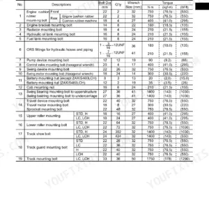
| Workshop Manual - General Information | 1075-1102 | Precautions for Disassembling and Assembling, Tightening, Painting, Bleeding Air From Hydraulic Oil Tank |
| Upperstructure Removal, Disassembly and Assembly | 1103-1392 | Cab, Counterweight, Main Frame, Pilot Shut-Off Solenoid Valve, 2-Spool Solenoid Valve Unit, Engine |
| Undercarriage Removal, Disassembly and Assembly | 1393-1502 | Swing Bearing, Center Joint, Track Adjuster, Front Idler, Upper and Lower Roller, Track |
| Front Attachment - Boom, Arm and Bucket | 1503-1552 | Cylinder |
Hitachi ZX110-3 - ZX135US-3 Common Problems This Manual Covers
Fault code on the monitor and the machine has derated or dropped into a limp condition
Start with the fault code tables in Troubleshooting A, which take each code to its likely causes and circuit checks. If it is an MC code, Troubleshooting B walks the electrical inspection connector by connector so you replace the failed part, not the controller.
Manual Section: Troubleshooting A - Fault Symptom DiagnosisSlow swing, weak digging force or long cycle times with no fault code set
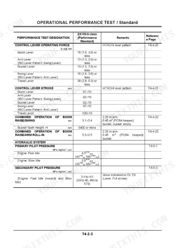
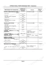
Run the machine against the factory numbers in the Operational Performance Test section - standard values, engine test, excavator test and component test procedures. Comparing measured cycle times and pressures against the standards tells you whether the fault is engine, pump or a single circuit before you open anything.
Manual Section: Operational Performance Test p. 379Track keeps coming loose, front idler wobbles or a roller is leaking oil
The Undercarriage Removal, Disassembly and Assembly section covers the track adjuster, front idler, upper and lower rollers and the track itself, with the disassembly sequence and assembly procedure for each. It also covers the swing bearing and center joint when the slop is higher up.
Manual Section: Undercarriage Removal, Disassembly and Assembly p. 1393Boom or arm cylinder drifting down or leaking past the rod seal
Cylinder disassembly and resealing is covered in the Front Attachment section of the Workshop Manual, and before you pull it apart, the cylinder drift measurements in the Operational Performance Test section confirm whether the leak is internal to the cylinder or sitting in the control valve.
Manual Section: Front Attachment - Boom, Arm and Bucket p. 1503Frequently Asked Questions
Does this manual include the full electrical wiring diagram and hydraulic circuit diagram?
No, and you should know that before buying. The printed manual had fold-out sheets attached to the back cover - the full electrical circuit diagram, connector charts, harness drawings and the hydraulic circuit diagram - and those sheets are not part of this PDF. What you DO get are the control-side system diagrams inside the text, like the ECM System diagram showing the main controller, CAN link, engine sensors, common rail, injectors and supply pump with colour-coded signal lines, plus written explanations of the pump control circuits.
Can I read and diagnose fault codes without the Dr. ZX dealer tool?
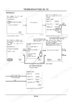
Mostly yes. The Troubleshooting volume covers the Dr. ZX tool, but it also walks you through the cab monitor unit, which displays fault codes on its own, and Troubleshooting A gives fault code tables plus symptom-based diagnosis for problems that never set a code. Troubleshooting B covers MC fault codes and step-by-step electrical checks with a multimeter at the connectors. Dr. ZX makes it faster, but the manual gives you the manual route.
My ZX135US-3 is slow and weak on all functions. Will this manual help me find out if it is the pump?
That is exactly what the Operational Performance Test section is for. It gives the standard values for engine speed, cycle times, travel speed and relief pressures, plus the test procedures to measure your machine against them. If the numbers point to the pump, the Component Operation section explains how the pump device and its control circuits are supposed to work, and the troubleshooting sections take you from symptom to cause before you condemn an expensive pump. p. 379
Which machines does this cover? I have a ZX130 with the blade.
It covers the whole ZAXIS-3 family in this size class: ZX110-3, ZX110M-3, ZX120-3, ZX130K-3, ZX130L-3, ZX135US-3, ZX135USK-3 and ZX135USL-3. The US machines are the ultra-short tail swing versions. One caution for blade machines: the hydraulic circuit diagram including the blade option was one of the fold-out sheets attached to the printed book, and those sheets are not in this PDF. p. 1
Does it actually cover tearing down components, or just theory and troubleshooting?
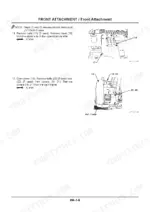
The third volume is the full Workshop Manual: removal, disassembly and assembly procedures for the cab, counterweight, main frame, engine, solenoid valve units, swing bearing, center joint, track adjuster, front idler, rollers, track and the boom, arm and bucket cylinders. It opens with the general precautions for disassembly and assembly, tightening specs and bleeding air from the hydraulic tank, so it is the volume you have open on the bench.
Reviews
There are no reviews yet.