
Part of the Hitachi Repair Manuals.
Boom speed drops off, the upperstructure jerks every time you stop a swing on a cold morning, or the monitor shows EC code 13 while the dealer tech is booked out for two weeks. This Hitachi EX200-3 and EX200LC-3 repair manual is for that moment.
It combines Technical Manual T137E-00 for circuits, performance tests and troubleshooting with Workshop Manual W137E-00 for teardown and rebuild. It covers the HPV091EW main pump, control valves and pilot circuit, plus the swing device, travel motors, track adjuster and cylinders. It also covers the Isuzu 6BD1TPJ engine. If you are on your own with the machine and nobody to call, the Dr.EX fault code lists and relief pressure specs tell you what to check next.
Print the sections you need and take them to the bench. A few hydraulic oil prints on the pages just means the book is earning its keep.
What's Inside This Hitachi EX200-3, EX200LC-3 Repair Manual
| System | Pages | Key Topics |
|---|---|---|
| Technical Manual: Safety & Specifications | 1-36 | Specifications, Working Ranges, Fuels and Lubricants, Refill Capacities, Machine Numbers, Component Specs |
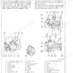
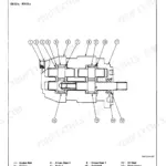
| Technical Manual: Upperstructure Components | 37-93 | Main Pump, Pilot Pump, Swing Device, Control Valve, Relief Valves, Pilot Valve, Solenoid Valves |
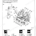
| Technical Manual: Undercarriage Components | 94-115 | Travel Reduction Gears, Travel Motor, Travel Brake Valve, Parking Brake, Center Joint, Track Adjuster |
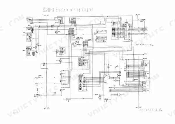
| Technical Manual: Electrical System | 116-189 | Main Circuits, Engine Start and Charging, EC/PVC Control System, Monitor, Fuses, Connectors, Fault Code Lists |
| Technical Manual: Hydraulic System | 190-217 | Hydraulic Circuit, Main and Pilot Circuits, Pump Control, Valve Control, Combined Operation |
| Technical Manual: Operational Performance Test | 218-295 | Engine Speed and Compression, Travel and Swing Tests, Drift Checks, Relief Pressure Settings, Pump Flow Test, Performance Standards |
| Technical Manual: Troubleshooting | 296-423 | Dr.EX Diagnosis, EC and PVC Fault Codes, Machine Malfunctions, Monitor and Indicator Faults, Harness Checks |
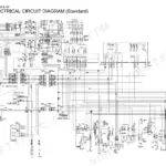
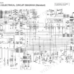
| Electric Wiring & Harness Diagrams | 424-426 | Electric Wiring Diagram, Engine Harness Diagram, Cab Harness Diagram |
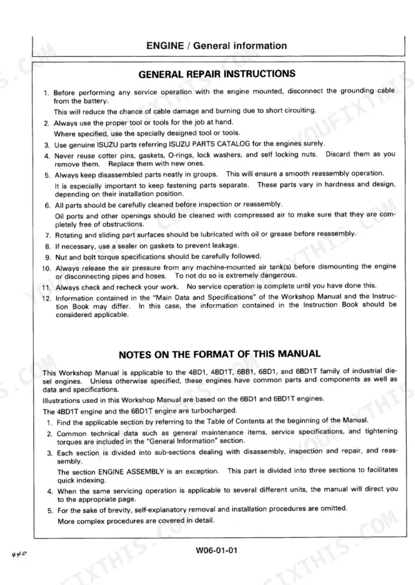
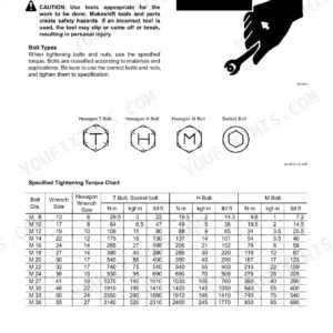
| Workshop Manual: General, Cab, Counterweight & Main Frame | 427-462 | Disassembly Precautions, Tightening Torque Chart, Cab Removal, Counterweight, Main Frame |
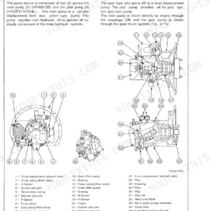
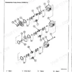
| Workshop Manual: Pump Device Repair | 463-492 | Remove/Install Pump Device, Main Pump and Pilot Pump Disassembly/Assembly |
| Workshop Manual: Control Valve Repair | 493-532 | Four-Section and Three-Section Control Valve Disassembly/Assembly |
| Workshop Manual: Swing Device Repair | 533-570 | Swing Reduction Gear, Swing Motor, Maintenance Standard |
| Workshop Manual: Pilot Valves, Shut-Off, Shockless Valve & Accumulator | 571-610 | Left/Right and Travel Pilot Valves, Pilot Shut-Off Valve, Shockless Valve, Accumulator |
| Workshop Manual: Solenoid, Shuttle & Swing Dampener Valves | 611-652 | Solenoid Valve Unit, Proportional Solenoid Valve, Relief and Reducing Valves, Shuttle Valve, Swing Dampener Valve |
| Workshop Manual: Undercarriage Repair | 653-778 | Swing Bearing, Travel Device and Motor, Brake Valve, Center Joint, Track Adjuster, Idler, Rollers, Track Link |
| Workshop Manual: Front Attachment & Cylinders | 779-816 | Front Attachment Removal, Cylinder Disassembly/Assembly, Maintenance Standards |
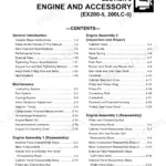
| Engine: General Information & Specifications | 817-844 | Isuzu Engine Main Data, Tightening Torques, Angular Tightening Method, Identification |
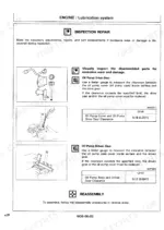
| Engine: Maintenance & Disassembly | 845-876 | Lubrication, Fuel and Cooling Service, Valve Clearance, Injection Timing, Compression Test, Disassembly |
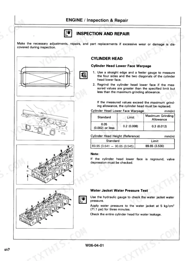
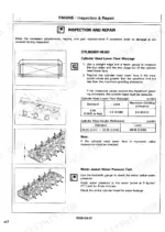
| Engine: Inspection & Repair | 877-904 | Cylinder Head, Valve Guides, Camshaft, Cylinder Liner, Pistons, Connecting Rod, Crankshaft, Flywheel |
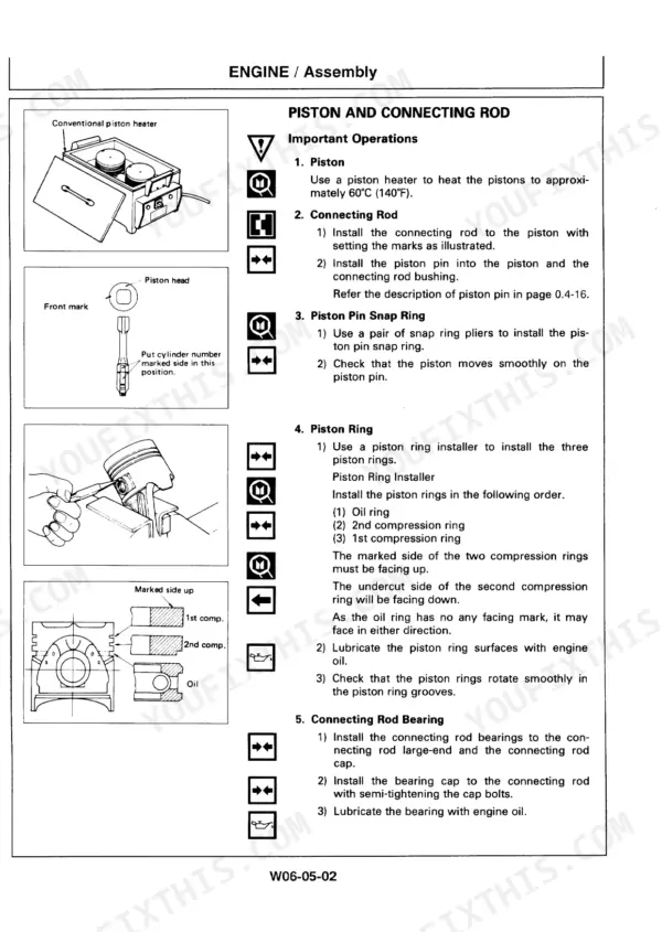
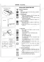
| Engine: Reassembly & Tuning | 905-932 | Piston and Rod Reassembly, Cylinder Head, Major Components, Engine Tuning Operation |
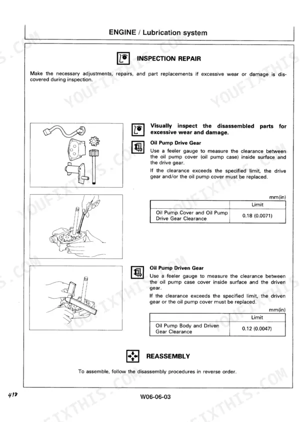
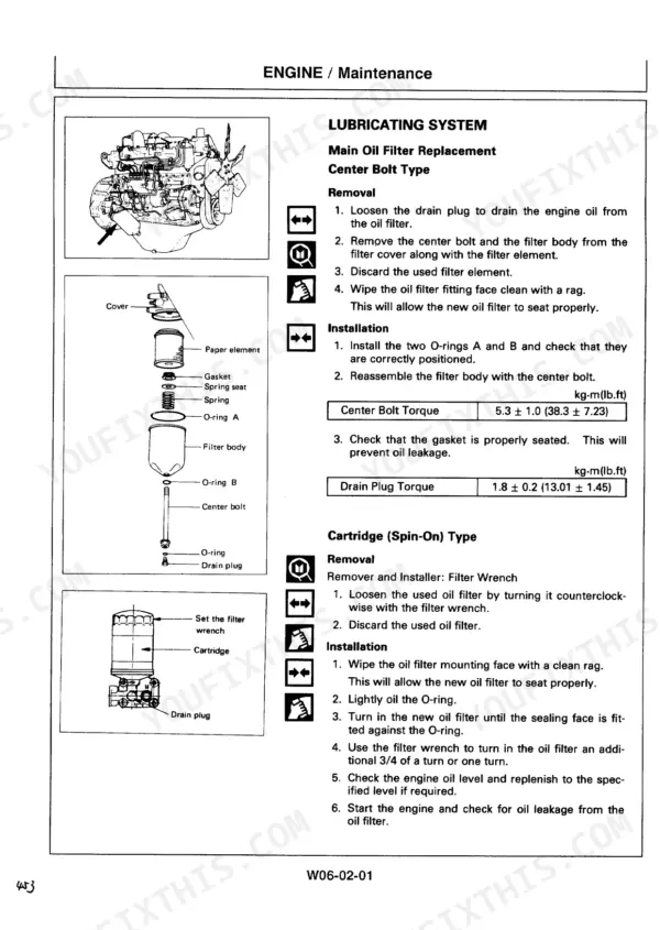
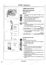
| Engine: Lubricating, Cooling & Fuel Systems | 933-962 | Oil Pump, Oil Filter, Oil Cooler, Water Pump, Thermostat, Injection Nozzle, Injection Pump Calibration |
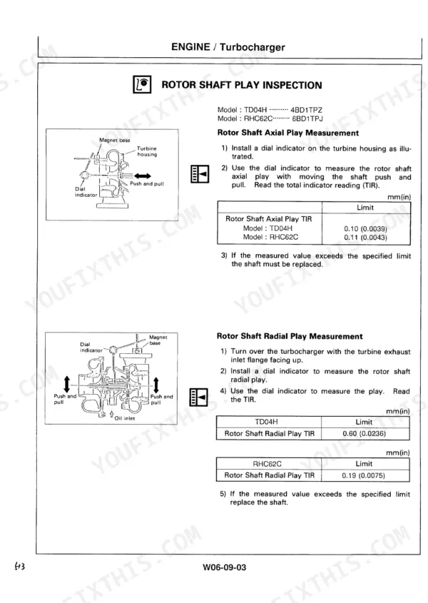
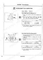
| Engine: Turbocharger, Air Compressor, Electricals & Troubleshooting | 963-1008 | Turbocharger, Air Compressor, Starter Motor, Alternator, Engine Troubleshooting, Special Tools |
Quick Reference Specifications
| Specification | Value | Page |
|---|---|---|
| Engine model | ISUZU 6BD1TPJ | p. 31 |
| Engine rated output | 99.3 kW / 2 050 min-1 (135 PS / 2 050 rpm) | p. 31 |
| Engine displacement | 5 785 cm3 | p. 31 |
| Firing order | 1-5-3-6-2-4 | p. 31 |
| Operating weight | 18 500 kg (40 800 lb) EX200-3; 19 000 kg (41 900 lb) EX200LC-3 | p. 14 |
| Bucket capacity (heaped) | PCSA 0.8 m3 (1.05 yd3), CECE 0.7 m3 | p. 14 |
| Fuel tank capacity | 310 L (82 US gal) | p. 19 |
| Engine oil capacity | 25 L (6.6 US gal) | p. 19 |
| Engine coolant capacity | 21 L (5.5 US gal) | p. 19 |
| Hydraulic system capacity | 200 L (52.8 US gal); hydraulic oil tank 130 L (34.3 US gal) | p. 19 |
| Main pump | HPV091EW, max. flow 187 L (49.4 US gal) x2 | p. 34 |
| Main relief pressure | 34.3 MPa (350 kgf/cm2, 4 977 psi) at 80 L/min | p. 34 |
| Overload relief pressure | 36.3 MPa (370 kgf/cm2, 5 261 psi) at 50 L/min | p. 34 |
| Swing speed | 11.0 min-1 (rpm) | p. 14 |
| Travel speed (fast/medium/slow) | 5.7/3.7/2.2 km/h (3.5/2.3/1.4 mph) | p. 14 |
Hitachi EX200-3, EX200LC-3 Common Problems This Manual Covers
Upperstructure jerks when swing stops, worse with cold oil
Troubleshooting B points to the swing dampener solenoid valve for this complaint. Confirm the diagnosis with the electrical checks in Troubleshooting. Then follow the Workshop Manual section on the solenoid, shuttle and swing dampener valves to pull the valve, inspect it and reassemble it.
Manual Section: Workshop Manual: Solenoid, Shuttle & Swing Dampener Valves p. 340Boom and arm will not move together in combined operation
Start with the valve control and combined operation pages in the Hydraulic System section. They explain how flow-dividing control splits pump oil between boom and arm. Once you know which spool or pilot signal is wrong, the Control Valve Repair section covers the four-section and three-section valves.
Manual Section: Technical Manual: Hydraulic System p. 207Slow boom, arm and bucket, weak digging force
Put gauges on and check main relief at 34.3 MPa at 80 L/min and overload relief at 36.3 MPa at 50 L/min. Follow the Operational Performance Test procedures for this, then run the pump flow test. If flow is below standard, Pump Device Repair covers the HPV091EW.
Manual Section: Technical Manual: Operational Performance Test p. 34Machine overheats under load
The monitor function pages say to take the load off and run at slow idle until coolant temperature drops, then start checking. Do not shut down a hot engine. Next, inspect the water pump, thermostat and oil cooler using the Lubricating, Cooling & Fuel Systems section of the Isuzu engine manual.
Manual Section: Engine: Lubricating, Cooling & Fuel Systems p. 166Frequently Asked Questions
What main relief pressure should an EX200-3 hold, and how do I check it?
Main relief is 34.3 MPa (350 kgf/cm2, 4 977 psi) at 80 L/min. Overload relief is 36.3 MPa (370 kgf/cm2, 5 261 psi) at 50 L/min. The Operational Performance Test section explains how to gauge the circuit and adjust the reliefs, and it lists the performance standards your readings should meet. p. 34
The monitor is showing EC fault code 13. What does that mean?
Code 13 means the EC controller sees the N sensor (engine speed sensor) as abnormal. The Troubleshooting section tells you to repeat the diagnostic procedure, check the N sensor harness, and then replace the sensor if the fault stays. Check the connectors and wiring before you buy a sensor. p. 315
Engine rpm falls well below the set speed as soon as I start digging. Where do I start?
The Basic Performance Check table lists this symptom as actual engine speed much slower than set speed. The causes it gives are reduced engine power or excessively increased main pump drive torque. Check the sensing signal from the A sensor and look for loss of engine power, then check operation of the stop motor before you suspect the pump. p. 271
What are the fluid capacities for an EX200-3 service?
The fuel tank holds 310 L (82 US gal). Engine oil is 25 L (6.6 US gal) and engine coolant is 21 L (5.5 US gal). The hydraulic system holds 200 L (52.8 US gal), and 130 L (34.3 US gal) of that is in the tank. Fuel and lubricant grades are in the Safety & Specifications section. p. 19
Does it go deep enough to rebuild the Isuzu engine?
Yes. The Isuzu 6BD1TPJ (5 785 cm3, firing order 1-5-3-6-2-4) has its own section. It covers inspection of the cylinder head, liners, pistons, rods and crankshaft, then reassembly, injection pump calibration, turbocharger, starter and alternator. One cylinder head job done in-house covers the cost of the book. p. 31
Reviews
There are no reviews yet.