
Part of the John Deere Repair Manuals.
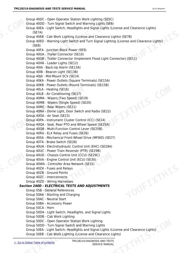
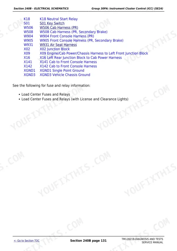
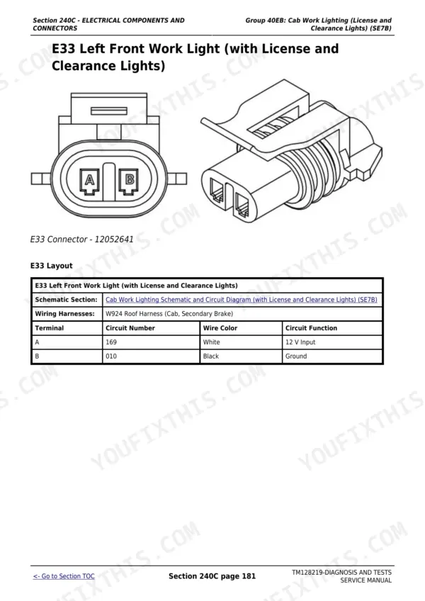
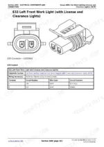
This is the complete John Deere factory diagnosis and tests service manual (TM128219) for the 5085E, 5095E and 5100E tractors equipped with the Interim Tier 4 emissions package. Across 2,332 pages it walks through every diagnostic path on the machine: reading and clearing Diagnostic Trouble Codes across all five control units, tracing faults with observable symptom trees, and performing calibrations, circuit tests and pressure checks on the 4045 PowerTech engine, fuel and air system, drive systems, transmission, steering, brakes, hydraulics and cab. The electrical chapters alone contain over 30 labeled circuit schematics, full harness and connector data, and test procedures with pass/fail limits so you work to factory specification the first time.
What's Inside This John Deere 5085E, 5095E, 5100E Manual
| System | Pages | Key Topics |
|---|---|---|
| General Information | Safety, General References, Technical Specific References, Specifications | |
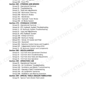
| Diagnostic Trouble Codes | Ccu Code Diagnostics, ECU Code Diagnostics, Eic Code Diagnostics, Icc Code Diagnostics, Ptr Code Diagnostics | |
| Observable Symptoms and System Diagnostics | Engine Diagnostics, Fuel/Air/Exhaust/Cooling Diagnostics, Electrical Diagnostics, ECU Diagnostics, Drive Systems and Transmission Diagnostics, Steering and Brakes Diagnostics, Hydraulic Diagnostics, Cab Diagnostics | |
| Engine | 4045 PowerTech Calibrations, Preliminary Checks, Theory of Operation, Engine Schematics, Component and Connector Information, Tests and Adjustments | |
| Fuel, Air Intake, Exhaust, and Cooling | Fuel System, Air Intake, Exhaust, Cooling Calibrations, Theory of Operation, Schematics, Component Information, Tests and Adjustments | |
| Electrical General and Theory of Operation | Turn Signal and Warning Lights, Wipers, Instrument Cluster Control (Icc), Electrohydraulic Control Unit (Ehc), Power Train Reverser (Ptr), Chassis Control Unit (Ccu), Engine Control Unit (ECU), Controller Area Network (CAN) | |
| Electrical Schematics | Key Switch/Starter/Alternator (SE1), Neutral Start (SE2), Accessory Power (SE3), Horn (SE4), Headlights and Signal Lights (SE5-SE8), Trailer Connector (SE10-SE11), Loader Lights (SE12), Back-Up Alarm and Beacon (SE13), Mid-Mount SCV (SE14), Power Outlets (SE15), Heating and Air Conditioning (SE16-SE17), Wipers (SE19-SE21), Instrument Cluster/ICC (SE24), EHC/PTR/CCU/ECU (SE29-SE30), CAN Bus (SE32) | |
| Electrical Components and Connectors | Starting and Charging, Fuses and Relays, Ground Points, Interconnects, Wiring Harnesses, Connector Locations | |
| Electrical Tests and Adjustments | Starting and Charging Tests, Lighting Tests, PTO and Seat Tests, Control Unit Tests, Alternator Output Verification | |
| Drive Systems and Transmission | Drive Systems Calibrations, Transmission Calibrations, Theory of Operation, Schematics, Component Information, Drive Systems Tests, Transmission Tests and Adjustments | |
| Steering and Brakes | Brake Calibrations, Steering Calibrations, Brake Theory of Operation, Secondary Brake Theory, Steering Theory, Brake and Steering Schematics, Component Information, Tests and Adjustments | |
| Hydraulics | Hydraulic Calibrations, General Hydraulics Theory, Mechanical Hitch Theory, Hydraulic Filter Theory, Hydraulic Pump Theory, Mid-Mount SCV, Rear SCV, Power Beyond, Quick Disconnect Coupler, Hydraulic Trailer Brake, Schematics, Tests and Adjustments | |
| Cab and Open Operator Station | HVAC Theory of Operation, Air Seat Theory, Schematics, Component Information, Tests and Adjustments | |
| Special Tools | General References, Dealer Fabricated Tools, Service Tools |
Quick Reference Specifications
| Specification | Value | Page |
|---|---|---|
| 5085E, 5095E, 5100E | ||
| Engine | John Deere 4045 PowerTech 4.5L, 4-cylinder turbocharged diesel, IT4/Stage IIIB, below 130 kW (174 hp) | |
| Power Train Reverser (PTR) | ||
| PTR Clutch Come-Home Mode Pressure | 1750 kPa (17.5 bar / 253 psi) | |
| PTR transmission clutch | ||
| Transmission Clutch Fill Pressure | 290 kPa | |
| All models | ||
| Alternator Output Voltage | 14.2-14.8 V | |
| Battery Full Charge Voltage | 12.65 V (specific gravity 1.265) | |
| Battery 75% State of Charge | 12.45 V (specific gravity 1.225) | |
| PTO Shaft Speeds | 540 rpm and 1000 rpm | |
| Hydraulic Oil Temperature Warning Threshold | Above 110 degrees C for more than 6 seconds triggers CCU code | |
| Engine Warm-Up Speed for Tests | 1200-1500 rpm | |
| Electrohydraulic Control Unit (EHC) | ||
| EHC Sensor Supply Voltage | 5.0 V | |
John Deere 5085E, 5095E, 5100E Common Problems This Manual Covers
CCU sensor supply voltage out of range (code CCU 003509) forces transmission to neutral
When the CCU sensor supply goes above 5.2 V or below 4.8 V it defaults the transmission to neutral to protect the drivetrain. The CCU code section directs you to perform the EHC Electrohydraulic Control Unit test first to isolate whether the fault is in the sensor reference circuit or the CCU itself, and to Recall, Record and Clear the code with the key in RUN before starting the engine for a recheck. Do not replace the CCU until the full diagnostic path is complete - the manual states control units are the least likely components to fail.
Manual Section: Diagnostic Trouble Codes - CCUTransmission shifts sluggishly or clutch engagement is abrupt after PTR code
Abrupt clutch engagement on the Power Train Reverser is caused by a clutch pedal released too quickly - the PTR monitors pedal release rate and restricts engagement speed when the pedal comes up fast. If the issue is paired with a PTR DTC, check the clutch pedal sensor A and B voltages (should stay within 0.03-4.7 V range) using the PTR diagnostic section before touching the transmission. The come-home mode pressure ceiling is 1750 kPa (17.5 bar), which the manual uses as a baseline for pressure circuit testing.
Manual Section: Drive Systems and TransmissionHydraulic system runs hot with a CCU temperature warning code
Hydraulic oil above 110 degrees C for more than 6 seconds triggers CCU 001638. Start with the hydraulic oil level and condition, then check the hydraulic filter - a clogged filter restricts return flow and drives fluid temperature up quickly during loader or hitch cycling. The Hydraulic Tests and Adjustments group gives the operational checks and pressure tests to confirm the filter and pump are within spec before suspecting the temperature sensor circuit itself.
Manual Section: Hydraulics - Section 270Tractor cranks slowly or fails to start after sitting
Slow cranking on the 4045 PowerTech engine points to low battery state of charge or a weak cell. Load-test the battery with an ammeter at 100 amps for 15 seconds to strip surface charge, then read voltage - below 12.4 V means the battery needs charging or replacement before the starter circuit can be condemned. The Starting and Charging test section walks through alternator output verification (14.2-14.8 V), checking for cell imbalance greater than 50 specific-gravity points between cells, and testing the neutral start circuit before moving to the starter motor.
Manual Section: Electrical Tests - Section 240DFrequently Asked Questions
How do I read and clear Diagnostic Trouble Codes on a John Deere 5085E or 5100E?
The manual covers DTC retrieval for all five control units: CCU (Chassis), ECU (Engine), EIC, ICC (Instrument Cluster) and PTR (Power Train Reverser). Each code section gives the exact fault threshold, control unit response, an operational check to confirm the fault, and a Recall/Record/Clear procedure. You work through the steps in order before replacing any component, since control units are the least likely parts to fail.
What does a CCU hydraulic oil temperature code mean and how is it diagnosed?
Code CCU 001638 activates when the hydraulic oil temperature sensor reads above 110 degrees C for more than 6 seconds. The CCU responds with an indicator alarm only. The diagnostic path starts with an operational check of the hydraulic oil temperature sensor voltage using CCU monitor function 010, then tests the sensor circuit for short to ground before clearing the code and confirming it does not return.
Why does the PTO shut off by itself on a 5085E tractor?
Automatic PTO shutdown is triggered by two CCU codes: overspeed (shaft more than 17% over 540 or 1000 rpm limit for 2 seconds, or more than 30% over immediately) and underspeed (shaft below 100 rpm for 5 seconds with PTO engaged). The diagnostic section walks through checking the PTO speed sensor signal using CCU monitors 005 and 058 before moving to the speed sensor circuit test and rear PTO system diagnosis.
How do I test the alternator and charging system on a John Deere 5100E?
The Electrical Tests and Adjustments section covers starting and charging diagnosis. A healthy alternator outputs 14.2-14.8 V. Battery state of charge is confirmed with a hydrometer and load tester - a fully charged battery reads 12.65 V and specific gravity of 1.265, while anything below 12.4 V under load requires further investigation before condemning the alternator.
Does this manual cover hydraulic SCV and remote outlet diagnosis?
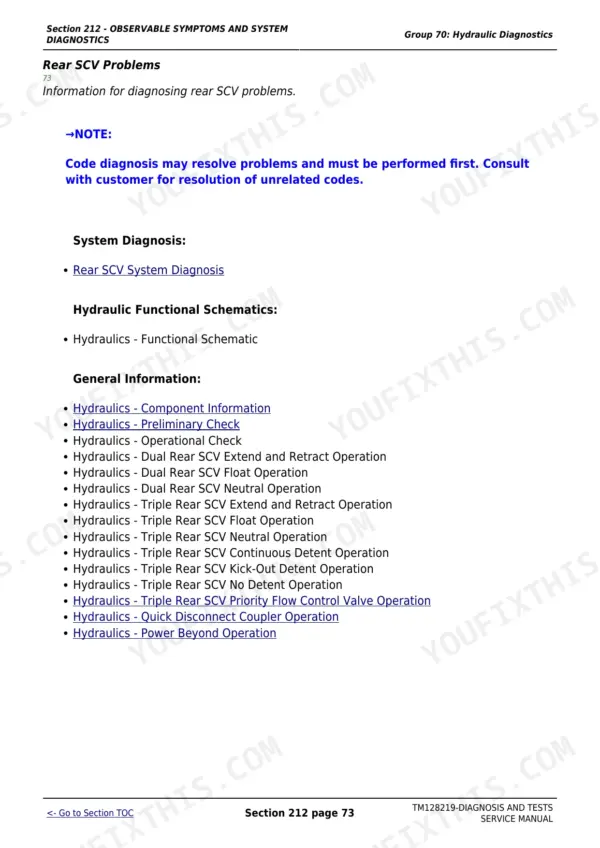
Yes. Section 270 covers hydraulic theory and tests for the mechanical hitch, hydraulic filter, hydraulic pump, dual and triple mid-mount SCVs, dual and triple rear SCVs, power beyond, quick disconnect couplers and hydraulic trailer brake. Observable symptom trees in Section 212 route hydraulic complaints to the correct test group, and the schematics and test procedures give pressure and flow limits for each circuit.
Is this John Deere 5085E manual a download or a disc?
A 2332-page Diagnostic in searchable PDF format (81 MB), available the moment you complete checkout. View on computer, tablet, or phone, with no shipping wait.
Can I print a copy of this John Deere 5085E Diagnostic for the shop?
Yes. Print the sections you need to take out to the shop for your own use. Standard letter or A4 paper works.








Reviews
There are no reviews yet.