


Part of the John Deere Repair Manuals.
This is the factory diagnostic manual for the John Deere 6010 series - 6010, 6110, 6210, 6310, 6410, 6510, 6610, 6810 and 6910, including SE and S builds, 1998 to 2005. It is the book you open when a light comes on or a system quits: service code diagnostics for every controller on the machine (BCU, BIF, ECU, HCU, PCU, PEC, PLC, RCU, SFA, TCU, UIC), symptom charts, functional schematics and wiring diagrams per build, circuit testing, and test values with real pressures and torques for the transmissions, hydraulics, steering, brakes and drive systems. It is a diagnostic manual, not a teardown book - disassembly and rebuild live in the separate repair manuals.
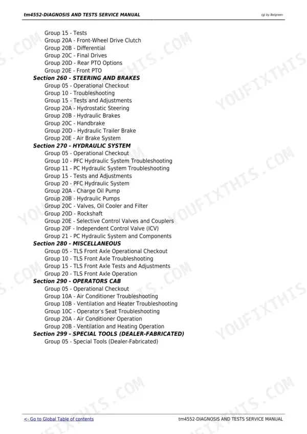
What's Inside This John Deere 6010 Series (6010-6910, SE and S) Manual
| System | Pages | Key Topics |
|---|---|---|
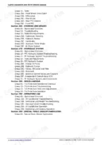
| Safety (Section 210) | 8-37 | Safe Operation and Service Practices, Safety Measures and Decal Locations for the 6010-6910 Tractors |
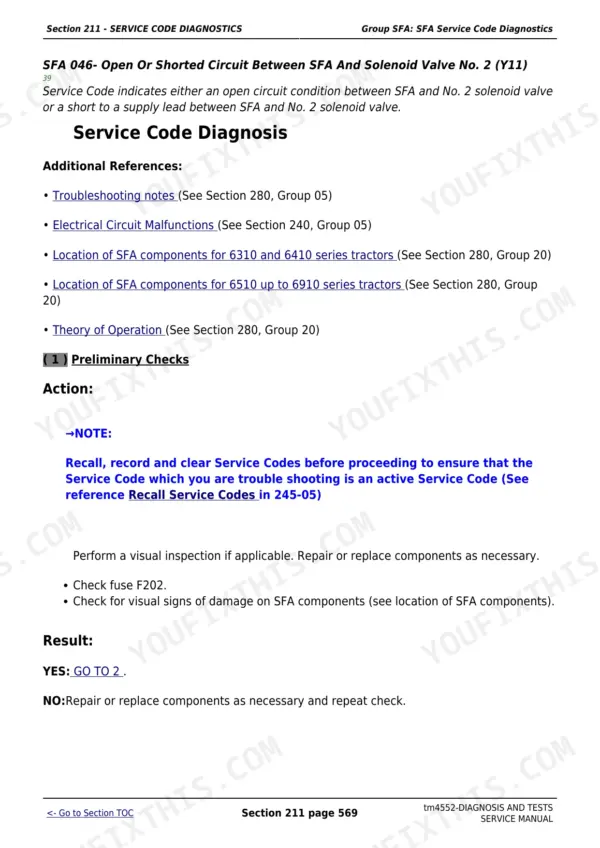
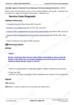
| Service Code Diagnostics (Section 211) | 38-1083 | Service Code Diagnostics for Twelve Controller Families: BCU, BIF, ECU (Level 1 with LUCAS Injection Pump), ECU (Level 4 with BOSCH VP44 Injection Pump), HCU, PCU, PEC, PLC, RCU, SFA, TCU and UIC |
| Observable Symptoms (Section 212) | 1084-1138 | Observable Symptom Charts for the Electrical System, PowrQuad/PowrQuad Plus/AutoQuad Transmissions, Drive System, Steering and Brakes and the Hydraulic System |
| Engine (Section 220) | 1139-1141 | Engine Tests |
| Fuel, Air Intake and Cooling Systems (Section 230) | 1142-1196 | System Diagnosis, Tests and Adjustments, Fuel System, Air Intake, Cooling System and Cold-Weather Starting Aids |
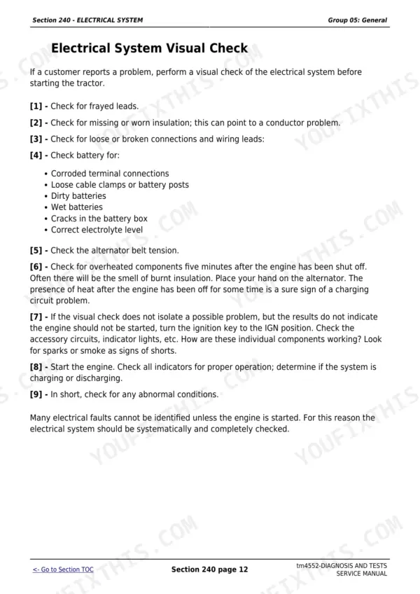
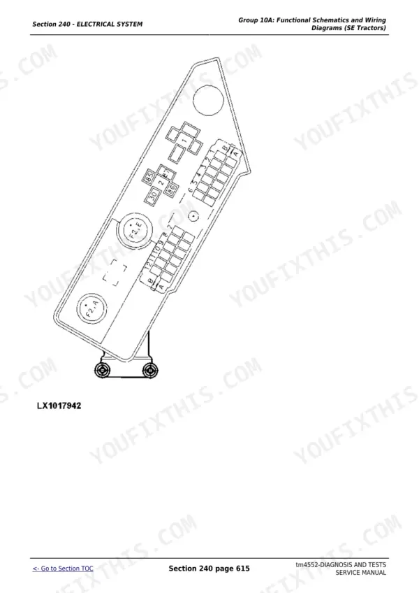
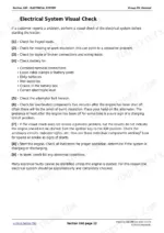
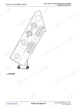
| Electrical System (Section 240) | 1197-3315 | Functional Schematics and Wiring Diagrams for Each Build - Cab Tractors, SE Tractors, 2-Post ROPS and AutoPowr - Plus Circuit Testing per Build, Sub-System Diagnostics, Data BUS Systems and Their Diagnosis, Adjustments and Component Testing |
| Electronic Control Units (Section 245) | 3316-4048 | Operation and General Information on Diagnostics, Then a Reference Group per Control Unit: BCU, BIF, ECU (Level 1), HCU, PCU, PEC, PLC, RCU, SFA, TCU, UIC |
| SyncroPlus Transmission (Section 250) | 4049-4175 | SyncroPlus: Operational Checkout, Troubleshooting, Tests and Adjustments, Transmission Operation, Perma Clutch II, Gear, Creeper and Range Transmission |
| Power Reverser Transmission (Section 251) | 4176-4295 | Power Reverser: Operational Checkout, Troubleshooting, Tests and Adjustments, Reverser Operation, Power Reverser Module, Gear Transmission |
| Power Shift Transmission (Section 252) | 4296-4435 | Power Shift: Operational Checkout, Troubleshooting, Adjustments, Theory of Operation |
| AutoPowr Transmission (Section 253) | 4436-4542 | AutoPowr: Diagnosis Via UIC, TCU and PLC, Tests and Adjustments, Operation |
| PowrQuad, PowrQuad Plus and AutoQuad II Transmissions (Section 255) | 4543-4752 | PowrQuad, PowrQuad Plus and AutoQuad II: Operational Checkout, Troubleshooting per Variant, Tests and Operation |
| Drive Systems (Section 256) | 4753-4825 | Operational Checkout, Troubleshooting, Tests, Front-Wheel Drive Clutch, Differential, Final Drives, Rear PTO Options and Front PTO |
| Steering and Brakes (Section 260) | 4826-4961 | Operational Checkout, Troubleshooting, Tests and Adjustments, Hydrostatic Steering, Hydraulic Brakes, Handbrake, Hydraulic Trailer Brake and Air Brake System |
| Hydraulic System (Section 270) | 4962-5295 | Operational Checkout, PFC and Pc Hydraulic System Troubleshooting, Tests and Adjustments, Charge Oil Pump, Hydraulic Pumps, Valves, Oil Cooler and Filter, Rockshaft, Selective Control Valves and Couplers, Independent Control Valve (ICV) |
| TLS Front Axle Suspension (Section 280) | 5296-5356 | Triple-Link Suspension Front Axle: Operational Checkout, Troubleshooting with the SFA Service-Code and Diagnostic-Address Lists, Calibration Mode, Nitrogen Precharge Notes, Relieving Hydraulic Pressure, Tests and Adjustments |
| Operator's Cab (Section 290) | 5357-5419 | Operator's Cab |
| Special Tools (Dealer-Fabricated) (Section 299) | 5420-5428 | Dealer-Fabricated Special Tools |
Quick Reference Specifications
| Specification | Value | Page |
|---|---|---|
| All models | ||
| Hydraulic system maximum system pressure | 19500 - 20500 kPa (195 - 205 bar) (2830 - 2970 psi) | p. 5039 |
| Hydraulic system minimum (standby) pressure | 2800 - 3300 kPa (28 - 33 bar) (406 - 479 psi) | p. 5040 |
| Rockshaft pressure relief valve | opens 20800 - 22200 kPa (208 - 222 bar), closes 17000 kPa | p. 5055 |
| Rockshaft valve sleeve torque | 90 N.m (66 lb-ft) | p. 5097 |
| Stepper motor to rockshaft valve screw torque | 10 N.m (8.5 lb-ft) | p. 5096 |
| Transmission lube oil pressure at 2300 rpm, oil at 45 C | 350 +/- 100 kPa (3.5 +/- 1 bar) (51 +/- 15 psi) | p. 4081 |
| Flow rate at the oil cooler, engine at 2300 rpm | 54 L/min (14.3 gpm) | p. 4087 |
| Power Reverser cooling oil pressure at 2300 rpm | 100 kPa (1 bar) (15 psi); zero with the clutch pedal fully depressed or fully released | p. 4212 |
| Shifter fork to shifter shaft threaded pin torque | 40 N.m (30 lb-ft) | p. 4091 |
| Shift cover to gear transmission cap screw torque | 30 N.m (22 lb-ft) | p. 4100 |
| Neutral start switch torque | 18 - 20 N.m (13 - 15 lb-ft) | p. 4102 |
| PTO solenoid valve coil resistance | 10 - 12 ohm at 20 C | p. 50 |
| PTO solenoid valve current, engaged | 1 - 1.2 A at 20 C and nominal 12 V | p. 48 |
| Differential lock solenoid valve coil resistance | 10 - 12 ohm at 20 C | p. 57 |
| MFWD solenoid valve coil resistance | 10 - 12 ohm at 20 C | p. 62 |
| Fuel tank level sender (service code BIF 16) | 0.5 - 4.0 V | p. 74 |
| Fuel tank level reading (service code BIF 31) | 0 - 100 percent | p. 76 |
| Coolant temperature reading (service code BIF 34) | 040 - 104 C | p. 82 |
| Coolant temperature sender (service code BIF 18) | 0.5 - 4.0 V | p. 93 |
| 6010-6510 | ||
| Transmission system (engagement) pressure at 2300 rpm | 1200 +/- 50 kPa (12 +/- 0.5 bar) (170 +/- 7 psi) | p. 4057 |
| Clutch pressure at 2300 rpm, 6010-6510 | 1200 +/- 50 kPa (12 +/- 0.5 bar) | p. 4077 |
| 6610 | ||
| Clutch pressure at 2300 rpm, 6610 | 1400 kPa (14 bar) - the 6610 runs a higher figure than the 6010-6510 | p. 4077 |
John Deere 6010 Series (6010-6910, SE and S) Common Problems This Manual Covers
Transmission tests 'low' on pressure - on a 6610 that was actually fine
The spec splits by model: clutch pressure at 2300 rpm is 1200 kPa plus or minus 50 on the 6010 through 6510, but 1400 kPa on the 6610. The transmission sections carry the tests per variant - SyncroPlus, Power Reverser, Power Shift, AutoPowr and PowrQuad each have their own, so you judge each tractor against its own figure instead of inventing a fault.
Manual Section: SyncroPlus Transmission (Section 250) - tests and adjustments p. 4077Fuel gauge or temperature gauge reads wrong and you cannot tell sender from instrument
Use the BIF service codes as live readouts: BIF 31 shows fuel level 0 to 100 percent, BIF 34 shows coolant temperature, BIF 16 and BIF 18 show sender voltage, spec 0.5 to 4.0 V. Section 211 walks each BIF code, so the meter work replaces the guesswork.
Manual Section: Section 211 - Service Code Diagnostics p. 76Electrical fault chased with the wrong schematic for the build
Cab tractors, SE tractors, 2-post ROPS and AutoPowr each carry their own functional schematics, wiring diagrams and circuit testing in Section 240. Identify your build first, then follow that build's diagrams and test steps - circuits differ between builds, and the wrong sheet sends you cutting into good harness.
Manual Section: Section 240 - Electrical SystemPTO, diff lock or MFWD will not engage and the solenoid is suspect
Section 256 gives the operational checkout, troubleshooting and tests for the drive systems, with hard electrical specs to test against: PTO, differential lock and MFWD solenoid coils all spec 10 to 12 ohm at 20 C, and the engaged PTO solenoid should draw 1 to 1.2 A at nominal 12 V.
Manual Section: Section 256 - Drive SystemsFrequently Asked Questions
My tractor is showing a code - will this manual tell me what it means?
Yes, if you read the code the way these tractors actually format it. There is no generic 'error 10' on a 6010 series - every code belongs to a controller family and reads like BCU 32 or BIF 34. The manual carries a full service code diagnostic section per controller: BCU, BIF, both ECU levels, HCU, PCU, PEC, PLC, RCU, SFA, TCU and UIC. Find your controller prefix, find the code, and it walks you through cause and test, step by step. p. 38
Do the wiring diagrams match my specific tractor?
Only if you match your build first, and the manual makes that easy to get wrong if you skip it. The schematics and circuit testing are split by build - cab tractors, SE tractors, 2-post ROPS and AutoPowr each get their own set. A wire that runs one way on a cab 6410 runs differently on an SE. Know which build you own before you put a meter on anything, then work from that build's diagrams. p. 1216
Which ECU section applies to my engine?
It depends on your injection pump, not your model number. The manual splits the engine controller by level: ECU Level 1 covers machines with the LUCAS injection pump, ECU Level 4 covers the BOSCH VP44 pump. The diagnostics are different between them, so identify the pump first. Get that wrong and you are chasing test values that were never meant for your engine. p. 159
Can I read live sensor values, or only stored faults?
The service codes double as live value addresses, which is the most useful trick in the book. BIF 34 reads coolant temperature in degrees, BIF 31 reads fuel level in percent, and the manual lists the healthy ranges - coolant reading 40 to 104 C, sender voltage 0.5 to 4.0 V. So instead of guessing whether a gauge or a sender is lying, you read what the controller actually sees and compare it against spec. p. 5039
Does this cover rebuilding the transmission or engine?
No, and it does not pretend to. This is the diagnostic manual: it gets you from symptom or service code to the failed component using checkouts, pressure tests, symptom charts and circuit testing. It covers operation and theory for SyncroPlus, Power Reverser, Power Shift, AutoPowr and the PowrQuad family, plus test specs and small assembly torques. Once you know what is broken, the separate repair manuals carry the teardown procedures. p. 4057








Reviews
There are no reviews yet.