
Part of the John Deere Repair Manuals.
This is the Diagnosis and Tests technical manual (TM134219) for 2015-2021 John Deere 5085M, 5100M, 5100MH, 5100ML, 5115M and 5115ML tractors. It is the book you open when a code appears or something quits: trouble-code diagnostics for the CCU, ECU, EIC, HCU, ICC, JDLink and PTR controllers, symptom charts, circuit-by-circuit electrical schematics with matching component locations and connector pinouts, plus live tests with real target values - relief pressures, clutch leak-check limits, cooler flows, hitch cycle times. Written for the Final Tier 4, CAN bus era of the 5M line, in both PowrReverser and SyncShuttle versions. Be clear on scope: this is the find-the-fault manual, not the teardown manual. Diagnose with a gauge and a meter instead of guessing.
Complete the set for your 5085M / 5100M / 5100MH / 5100ML / 5115M / 5115ML
What's Inside This John Deere 5085M / 5100M / 5100MH / 5100ML / 5115M / 5115ML Manual
| System | Pages | Key Topics |
|---|---|---|
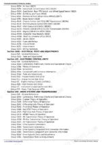
| General Information (Section 210) | 10-54 | Safety, General References, Technical Specification References |
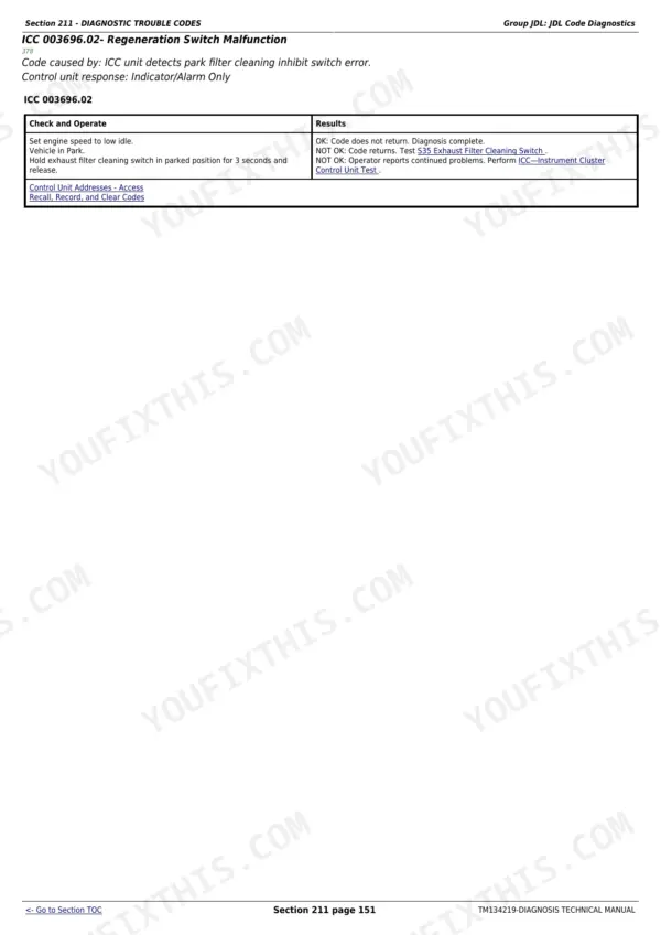
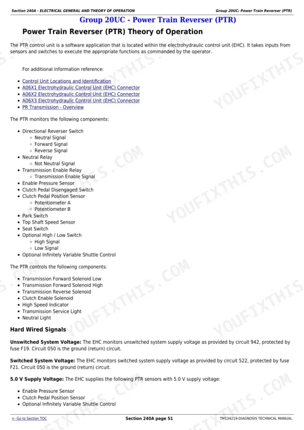
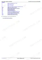
| Diagnostic Trouble Codes (Section 211) | 55-249 | Code Diagnostics for All Seven Controller Families: CCU (Chassis Control Unit), ECU (Engine Control Unit), EIC, HCU (Hitch Control Unit), ICC (Instrument Control Cluster), JDLink and PTR (Power Train Reverser) |
| Observable Symptoms and System Diagnostics (Section 212) | 250-336 | Observable Symptom Charts and System Diagnostics for Engine, fuel/air/exhaust/cooling, Electrical, Control Units, Drive Systems and Transmission, Steering and Brakes, Hydraulics and the Operator Station |
| Engine (Section 220) | 337-344 | Engine Component and Connector Information, Engine Tests and Adjustments |
| Fuel, Air Intake, Exhaust, and Cooling (Section 230) | 345-356 | Fuel, Air Intake, Exhaust and Cooling Theory of Operation |
| Electrical General and Theory of Operation (Section 240A) | 357-423 | Electrical Theory of Operation: Turn Signal and Warning Lights, Wipers, Instrument Cluster Control, Electrohydraulic Control, Hitch Control, PowrReverser, Chassis Control Unit for Both PR and SS Transmissions, Engine Control Unit, CAN Bus |
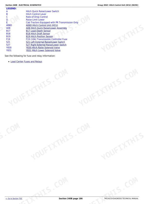
| Electrical Schematics (Section 240B) | 424-656 | Circuit-By-Circuit Electrical Schematics (SE01 to SE34): Key switch/starter/alternator, Neutral Start for SS and PR Transmissions, Accessory Power, Horn, Lighting, Warning Lights, Junction Block, Implement Connector, SCV, Heating and Air Conditioning, Wipers, Control Units, CAN, AutoTrac, JDLink |
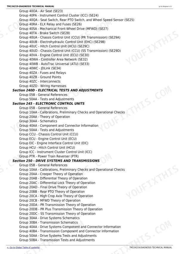
| Electrical Components and Connectors (Section 240C) | 657-1247 | Component Locations and Connector Pinouts for Every Se Circuit, Plus Fuses and Relays, Ground Points, Interconnects and Wiring Harnesses |
| Electrical Tests and Adjustments (Section 240D) | 1248-1305 | Electrical Tests and Adjustments: Alternator Output, CAN Bus Voltages, Circuit and Connector Checks |
| Electronic Control Units (Section 245) | 1306-1385 | Calibrations and Operational Checks, Theory of Operation, Schematics, Component and Connector Information, Tests and Adjustments, And a Dedicated Group per Controller: CCU (Chassis Control Unit), ECU (Engine Control Unit), EIC (Engine Interface Control Unit), HCU (Hitch Control Unit), ICC (Instrument Cluster Control Unit), PTR (Power Train Reverser) |
| Drive Systems and Transmissions (Section 250) | 1386-1602 | Calibrations and Operational Checks, Creeper, Differential and Differential Lock, Final Drive, Rear PTO, High Crop Axle, MFWD, And Theory of Operation for All Three Transmissions: PR (PowrReverser), PR Plus and SS (SyncShuttle); Clutch Leak Checks and Pressure Tests |
| Steering and Brakes (Section 260) | 1603-1649 | Brake and Steering Calibrations and Operational Checks, Theory of Operation, Brake and Steering Schematics, Component and Connector Information, Brake and Steering Tests and Adjustments |
| Hydraulics (Section 270) | 1650-1779 | Hydraulic Calibrations and Operational Checks, General Hydraulics Theory, Electrohydraulic Hitch, Mechanical Hitch, Front Hitch, Filter and Pump, Dual and Triple Mid-Mount SCV, Power Beyond, Quick Disconnect Couplers, Dual and Triple Rear SCV, Functional Schematics, Tests and Adjustments |
| Cab / Open Operator's Station (Section 290) | 1780-1819 | HVAC and Seat Theory of Operation, Schematics, Component and Connector Information, Calibrations and Tests and Adjustments |
| Special Tools (Section 299) | 1820-1824 | Dealer-Fabricated and Service Tools |
Quick Reference Specifications
| Specification | Value | Page |
|---|---|---|
| All models | ||
| Main relief valve pressure | 19000 - 20000 kPa (190 - 200 bar) (2756 - 2901 psi) | p. 1775 |
| Hitch cylinder supply pressure (raise) | 19000 - 20000 kPa (190 - 200 bar) | p. 1766 |
| Hitch load-sense relief pressure | 19000 - 20000 kPa (190 - 200 bar) | p. 1768 |
| Implement relief valve pressure | 19000 - 20000 kPa (190 - 200 bar) | p. 1772 |
| Mechanical hitch surge relief valve cracking pressure | 23000 - 24000 kPa (230 - 240 bar) | p. 1769 |
| Rear SCV detent kick-out pressure | 16000 - 19000 kPa (160 - 190 bar) | p. 1774 |
| Triple mid-mount SCV maximum flow | 40 L/min (10.5 gpm) | p. 1771 |
| Implement pump standby pressure (controls in neutral) | 0 - 500 kPa (0 - 5 bar) | p. 1776 |
| Hitch cycle raise time | 2.5 - 3.5 seconds | p. 1676 |
| Hitch settling wear limit | 56 mm cylinders: max 3.0 mm (0.12 in.) drop in 15 minutes | p. 1676 |
| SCV pressure hold | stays above 3450 kPa (34.5 bar) for at least 5 seconds | p. 1778 |
| Steering relief valve pressure (full left turn) | 13000 - 13700 kPa (130 - 137 bar) (1885 - 1987 psi) | p. 1647 |
| Steering pump minimum flow (1000 rpm at 150 bar) | 10.6 L/min (2.8 gpm) | p. 1646 |
| Transmission system 1 pressure (steering neutral) | 1150 - 1250 kPa (11.5 - 12.5 bar) | p. 1645 |
| Brake retractor adjustment pressure | 3000 - 4000 kPa (30 - 40 bar) | p. 1642 |
| System 2 pressure at 1000 rpm | 1100 - 1200 kPa (11.0 - 12.0 bar) | p. 1600 |
| System 1 preliminary pressure at 1000 rpm | 1200 kPa (12 bar) (174 psi) | p. 1579 |
| Engagement override valve (EOV) pressure at 1000 rpm | 1200 kPa (12 bar) | p. 1597 |
| MFWD / PTO clutch / differential lock engaged pressure | 1200 kPa (12 bar) (174 psi) | p. 1571 |
| Clutch and MFWD leak-check wear limit | maximum differential pressure 17 kPa (0.17 bar) (2.5 psi) | p. 1570 |
| System 2 to clutch leak-check limit | maximum pressure difference 207 kPa (2.07 bar) (30 psi) | p. 1581 |
| Alternator output | 90 A at 13.2 V (open station) / 120 A at 13.2 V (cab) | p. 1279 |
| CAN bus voltages | CAN Hi circuit 9914: 2.50 - 3.50 V | p. 1290 |
| EH hitch valve raise solenoid nut torque | 10 +/- 1 N.m (7 +/- 1 lb-ft) | p. 1358 |
| Air conditioning compressor clutch air gap | 0.35 - 0.65 mm (0.014 - 0.026 in.) | p. 1814 |
| A/C test coupling valve stem depth | 7 - 7.6 mm (0.275 - 0.300 in.) | p. 1812 |
| PowrReverser (PR) transmission | ||
| Transmission cooler flow at 1000 rpm, PowrReverser (PR) transmission | 8.3 L/min (2.19 gpm) | p. 1594 |
| SyncShuttle (SS) transmission | ||
| Transmission cooler flow at 1000 rpm, SyncShuttle (SS) transmission | 10.4 L/min (2.45 gpm) | p. 1594 |
John Deere 5085M / 5100M / 5100MH / 5100ML / 5115M / 5115ML Common Problems This Manual Covers
PowrReverser clutch slipping or tractor creeping, and you dread splitting it to find out why
The drive systems section diagnoses clutch packs with a gauge, not a split. Engaged clutch pressure should read 1200 kPa (174 psi); the leak check allows at most 17 kPa (2.5 psi) differential, and system 2 to clutch at most 207 kPa. Out of limit points to the leaking pack before you pull anything apart.
Manual Section: Drive Systems And Transmissions (Section 250) p. 1583Tractor will not crank, or cranks only in certain lever positions
Neutral start is transmission-specific: the schematics section carries separate SS and PR neutral-start circuits alongside the key switch, starter and alternator circuit. Confirm your transmission first, then trace that exact SE circuit through its schematic, component locations and connector pinouts to the open switch or broken wire.
Manual Section: Electrical Schematics (Section 240B) p. 438Multiple controllers logging communication codes at once, dash acting possessed
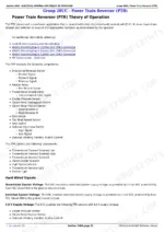
That pattern usually means CAN bus trouble, not seven failed controllers. The electrical theory section explains how the CCU, ECU, cluster and the rest talk on the bus, and the tests give a hard target: CAN Hi circuit 9914 should measure 2.50 to 3.50 V. Chase the bus wiring before condemning modules.
Manual Section: Electrical General And Theory Of Operation (Section 240A) p. 1290Steering feels heavy or slow and you are not sure if it is the pump or the valve
The steering and brakes section pins it down with two measurements: steering relief at full left turn should read 13000 to 13700 kPa (1885 to 1987 psi), and the steering pump must deliver at least 10.6 L/min at 1000 rpm against 150 bar. Low flow condemns the pump; low relief points at the valve.
Manual Section: Steering And Brakes (Section 260) p. 1647Frequently Asked Questions
My 5085M is showing a fault code on the dash. Will this manual tell me what it means and how to clear it?
Yes, that is the core of the book. It carries diagnostics for the codes thrown by every controller on these tractors: CCU (chassis), ECU (engine), EIC, HCU (hitch), ICC (instrument cluster), JDLink and PTR (PowrReverser). Each diagnostic walks you to the failed circuit or component. One honest note: there is no magic reset button trick. A code clears and stays cleared when the cause is fixed, and that is exactly what these procedures are built to find. p. 55
My 5100M transmission threw a fault. Where do I start?
Start by confirming which transmission you have, because these tractors came as PowrReverser (PR) or SyncShuttle (SS) and the manual splits accordingly: separate neutral-start schematics, separate CCU diagnostic groups, even different cooler flow targets (8.3 L/min for PR vs 10.4 L/min for SS at 1000 rpm). Follow the wrong branch and you chase ghosts. PowrReverser faults land in the PTR code family, and the drive systems section backs the codes with pressure tests you run with a gauge. p. 1594
How good is the electrical coverage? These tractors have a lot of wiring.
This is where the book earns its keep. The electrical half is circuit by circuit: for each SE-numbered circuit (key switch and starter, lighting, SCV, HVAC, CAN, AutoTrac, JDLink and so on) you get the schematic, then the component locations, then the connector pinouts for that same circuit. That triple view is what turns a wiring fault from guesswork into a findable break: read the schematic, walk to the connector, put a meter on the exact pin. p. 424
Does it have torque specs for things like wheel lug nuts, or engine rebuild specs?
No, and better you know before buying. This is the diagnosis and tests manual: it carries test targets and adjustment values (relief pressures, voltages, cycle times, items like the EH hitch raise solenoid nut at 10 N.m), not general assembly torques or teardown specs. Wheel hardware torques and rebuild procedures live in the operator's manual and the separate repair manual. If your problem is 'what is wrong with it', this is the right book. If it is 'how do I rebuild it', it is not. p. 1358
The hitch and hydraulics feel weak. Can I actually test them with this manual?
Yes, with numbers instead of feel. Main relief should hold 19000 to 20000 kPa (190 to 200 bar), same target for hitch supply and implement relief. Pump standby with controls in neutral is 0 to 500 kPa. The hitch itself has pass/fail wear checks: a full raise in 2.5 to 3.5 seconds, and on 56 mm cylinders no more than 3.0 mm of settle in 15 minutes. SCV detent kick-out is 16000 to 19000 kPa. One gauge tells you pump, valve or cylinder. p. 1676







Reviews
There are no reviews yet.