Part of the John Deere Repair Manuals.
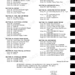
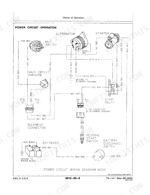
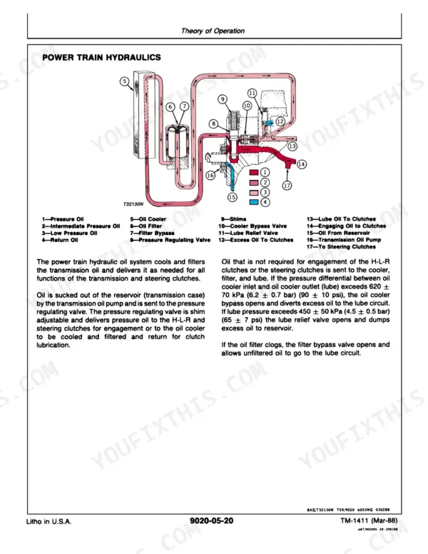
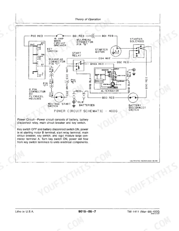
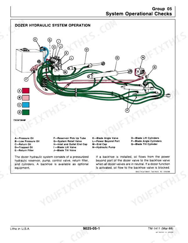
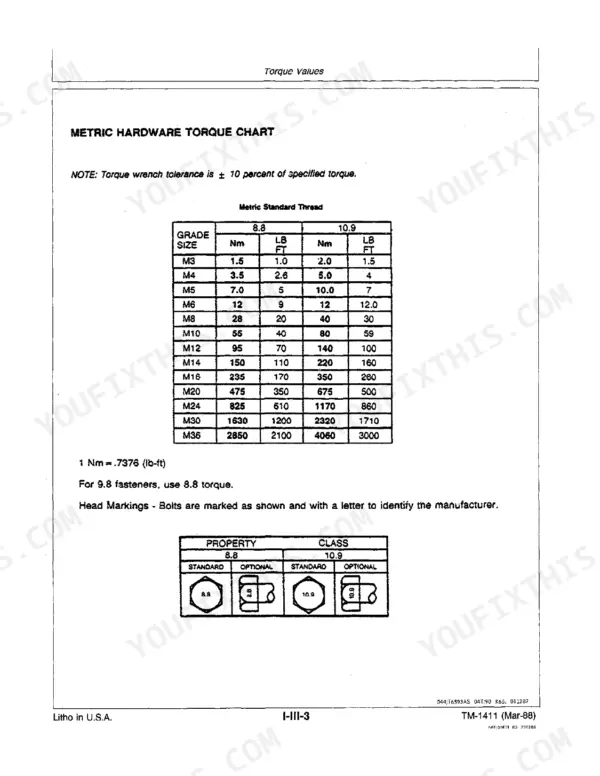
Pinning down why a John Deere 400G crawler bulldozer won't run right is the job these 272 pages of factory Operation and Test data (TM-1411) are written for, and this John Deere 400G technical manual PDF hands you all of it. Electrical faults get traced on wiring diagrams that follow each circuit through switches and connectors, while hydraulic schematics map oil flow from the pump through the control valve to the cylinders. After General Information (torque values, fuels and lubricants) and the operational checkout, the engine, electrical, power train and hydraulic chapters run from theory of operation through system checks, diagnostics and tests, ending with miscellaneous components. Check that the air restriction indicator lights at 6.2 kPa (25 in. water), and set track sag to 22-29 mm (7/8-1-1/8 in.). Searchable, bookmarked text finds the right test fast.
What's Inside This Manual
| System | Pages | Key Topics |
|---|---|---|
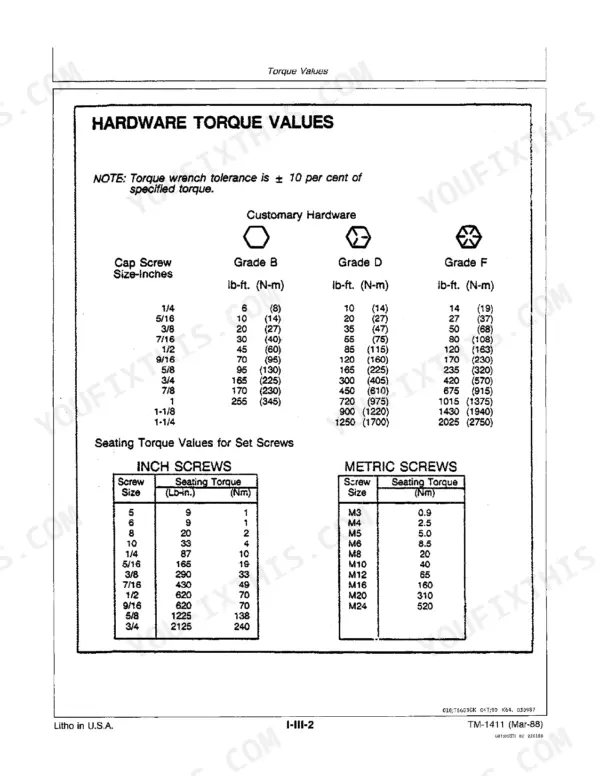
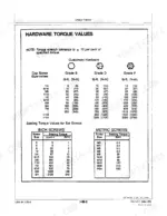
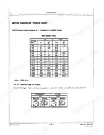
| General Information | 1-32 | Safety Precautions, General Specifications, Torque Values, Fuels and Lubricants |
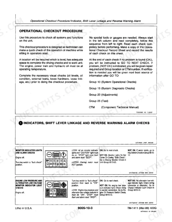
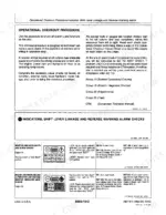
| Operational Checkout Procedure | 33-50 | Operational Checkout Record |
| Engine Operation and Test | 51-98 | Theory of Operation, System Operational Checks, Diagnostic Information, Adjustments, Tests, Cooling System, Radiator Cap, Thermostat, Fuel Injection Pump, Compression Pressure, Engine Oil Pressure |
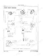
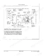
| Electrical System Operation and Test | 99-166 | Theory of Operation, System Operational Checks, Diagnostic Information, Tests, Starting Circuit, Charging Circuit, Starting Motor, Ground Locations, Work Light Circuit |
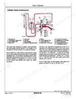
| Power Train Operation and Test | 167-226 | Theory of Operation, System Operational Checks, Diagnostic Information, Adjustments, Tests, Power Train Block Diagram, Track Sag, Transmission Oil Filter Inspection, Steering Valve Operation, Transmission System Pressure |
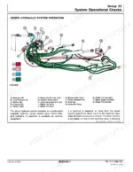
| Hydraulic System Operation and Test | 227-252 | Theory of Operation, System Operational Checks, Diagnostic Information, Tests, Dozer Blade Lift Valve, Dozer System Relief Valve, Cylinder Leakage, Dozer Cylinder Drift, Hydraulic Oil Filter Inspection |
| Miscellaneous Components | 253-272 | Theory of Operation, Diagnostic Information, Adjustments, Tests |
Quick Reference Specifications
| Specification | Value | Page |
|---|---|---|
| Battery Reserve capacity | 180 minutes | p. 14 |
| O-ring boss fitting torque (3/8-24 UNF) | 8 Nm (6 lb-ft) | p. 20 |
| O-ring boss fitting torque (7/16-20 UNF) | 12 Nm (9 lb-ft) | p. 20 |
| Outside diameter of a new bushing | 44.5 mm (1.75 in.) | p. 199 |
| Air restriction indicator vacuum trip point | 635 mm (25 in.) water | p. 55 |
| Oil filter bypass valve differential opening pressure | 370 kPa (3.7 bar) (54 psi) | p. 57 |
| Fan belt deflection | 3/4-in. with 20 lb push | p. 67 |
| Volts | 12 volts | p. 103 |
| Minimum recommended bushing outside diameter (normal loading) | 39.6 mm (1.56 in.) | p. 199 |
| Hydraulic warm-up temperature | 40°C (100°F) | p. 237 |
| System Relief Valve Pressure | 151510 + 1380 - 0 kPa (2250 + 200 - 0 psi) | p. 248 |
| Hydraulic Pump Flow (New) | 5.37 L/min (14.2 gpm) | p. 249 |