
Part of the John Deere Repair Manuals.
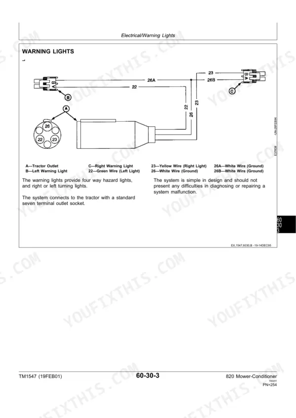
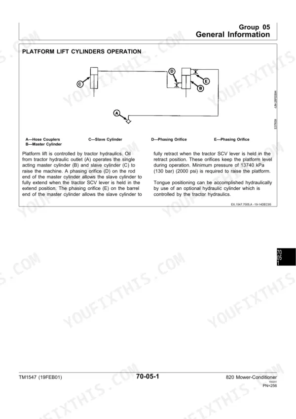
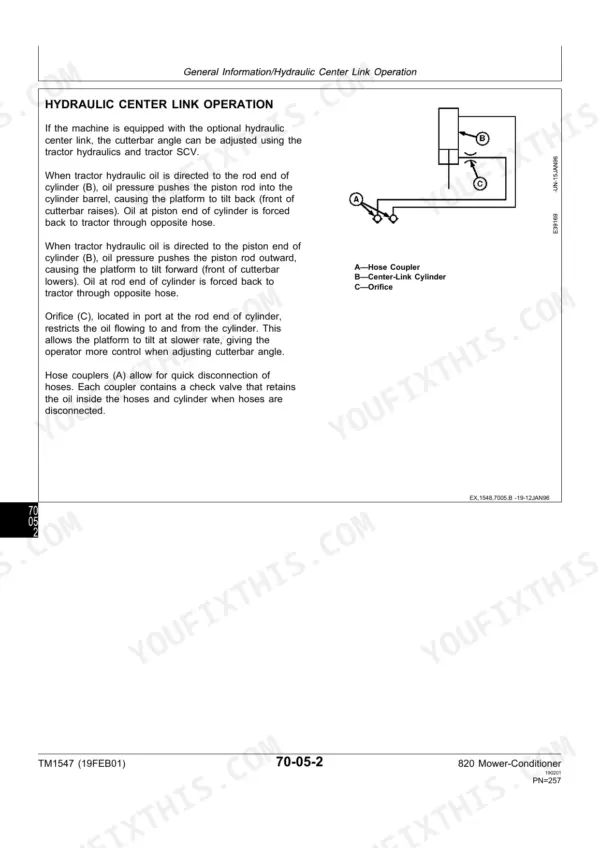
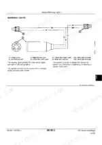
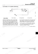
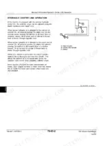
Rebuilding a cutterbar or pulling conditioner rolls goes smoother with 298 pages of John Deere factory instruction behind you: the John Deere 820 technical manual PDF, TM1547, written for the 820 Mower-Conditioner. Near the back, diagrams show how the hydraulic lift cylinders and center link work, and page 267 carries the warning light wiring diagram. Close to a third of the pages go to the conditioner alone, covering roll arms, bearings, and roll service, while the power train section walks the PTO hookup, driveline, and slip clutch from teardown through reassembly. Set drive belt deflection at 8 mm (5/16 in.) under 89 to 125 N (20 to 28 lb) of pull, and torque bolt-on knife section nuts to 11 N·m (8 lb-ft). A guessed torque on a knife section shows up as a broken blade mid-field. Pages are crisp and print-ready, bookmarked for jumps, and once downloaded the file stays yours as long as the 820 does.
What's Inside This John Deere 820, 820 Mower-Conditioner Manual
| System | Pages | Key Topics |
|---|---|---|
| General | 7-24 | Safety, Specifications (Machine Specifications, Cap Screw Torque Values, Machine Description), Lubrication (Main Drive Gear Case Oil, Cutterbar Drive Gear Case Oil, Grease) |
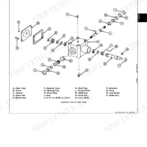
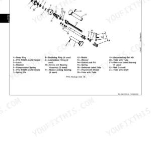
| Power Train | 25-98 | PTO Hookup, Driveline, Slip Clutch, Main Drive Gear Case |
| Cutting Components | 99-126 | Cutterbar |
| Platform | 127-162 | Platform Components, Reel |
| Conditioner | 163-246 | Roll Arms and Bearings, Rolls |
| Carrier Frame | 247-268 | Carrier Frame Components, Tongue, Wheel Hub and Support |
| Hydraulics | 269-288 | Hydraulic Lift Cylinders, Hydraulic Center Link |
| Tools | 289-294 | Special Tools, Fabricated Tools |
Quick Reference Specifications
| Specification | Value | Page |
|---|---|---|
| Metric Bolt and Cap Screw Torque (Class 8.8 or 9.8, M6) | 9 N·m (6.5 lb-ft) lubricated, 11 N·m (8.5 lb-ft) dry | p. 19 |
| Metric Bolt and Cap Screw Torque (Class 8.8 or 9.8, M8) | 22 N·m (16 lb-ft) lubricated, 28 N·m (20 lb-ft) dry | p. 19 |
| Conditioner drive belt deflection | 8 mm (5/16 in.) with 89-125 N (20-28 lb) pull | p. 201 |
| Cutterbar drive belt deflection | 8 mm (5/16 in.) with 89-125 N (20-28 lb) pull | p. 88 |
| Bolt-on knife section nut torque | 11 N·m (8 lb-ft) | p. 109 |
| Knife Guard Vertical Alignment | ± 3 mm (0.1 in.) | p. 102 |
| Guard bolt torque | 61-68 N·m (45-50 lb-ft) | p. 110 |
| Reel Drive Chain Deflection | 8-12 mm (5/16-1/2 in.) | p. 166 |
John Deere 820, 820 Mower-Conditioner Common Problems This Manual Covers
Main drive slip clutch slips excessively during operation
The driveline chart on page 31 names four causes: ground speed too high, loose slip clutch bolts, grease or oil on the clutch facings, and glazed facings. Slow down first. If it still slips, adjust the slip clutch, clean or replace oil-soaked facings, and install a new slip clutch lining when the facings are glazed (Group 25 of the Power Train section).
Manual Section: Diagnose Driveline Malfunctions p. 31Stems shredding, leaf damage or leaf loss as crop passes through the conditioner rolls
Page 167 traces all three to roll pressure: set too high or set incorrectly, it overconditions the crop. Decrease roll pressure using Adjust Roll Pressure in Group 20 of the Conditioner section. If the rolls plug, stop the engine and disengage the PTO, wait until every moving part has stopped, then remove the foreign objects.
Manual Section: Diagnosing Conditioner Malfunctions p. 167Cutterbar leaving long or uneven stubble
The cutterbar chart on page 104 points to a dull knife, excessive ground speed, a worn or damaged cutterbar, float springs out of adjustment, a loose cutterbar drive belt, wrong cutting height, or a guard angle that is too flat. Replace a dull knife, cut at a lower ground speed while holding rated PTO speed, retension the cutterbar drive belt, and reset the gauge shoes.
Manual Section: Diagnosing Cutterbar Malfunctions p. 104Platform does not raise evenly on the hydraulic lift cylinders
Page 273 lists air in the line between the master and slave cylinder, a plugged orifice at the master cylinder output port, and worn piston seals. Bleed the lift cylinders first, then clear the orifice or recondition the master cylinder, and recondition any cylinder with worn seals (Group 15 of the Hydraulics section).
Manual Section: Diagnosing Hydraulic Lift Cylinder Malfunctions p. 273Frequently Asked Questions
What is the torque specification for John Deere 820 wheel bolts?
The torque specification for the wheel bolts on the John Deere 820 is 115 N·m (85 lb-ft). p. 261
What are the replacement specifications for John Deere 820 sickle sections?
When replacing bolt-on knife sections, install each new section with two rib neck bolts and lock nuts. Tighten the nuts to 11 N·m (8 lb-ft). p. 109
How do you fix John Deere 820 sickle sections breaking and the knife bar cutting unevenly across the cutterbar?
Replace cracked or dull sections and torque the bolt-on knife section nuts to 11 N·m (8 lb-ft), as page 109 lists. Check guard vertical alignment within ± 3 mm (0.1 in.) and pull guard bolts to 61-68 N·m (45-50 lb-ft). Set hold-down clearance with a 0.13 mm (0.005 in.) feeler gauge before first cutting this season. p. 109
What makes the John Deere 820 PTO hookup vibrate excessively?
The driveline chart on page 31 lists a bent or twisted hookup tube or shaft, the tractor running at an excessive angle to the mower-conditioner, and worn universal joint cross bearings. Straighten or replace the tube or shaft, check hookup dimensions to reduce the angle, and replace the U-joint bearings using the Group 15 procedure. For excessive noise, the same chart says to run the PTO at 540 rpm. p. 31
How is this John Deere 820 Technical Manual delivered?
This is a 298-page non-searchable PDF ready for immediate download. Works on any device, so pull it up on your phone while you're under the hood. No shipping, no waiting.
Can I print this John Deere 820 manual?
You can. Print the sections you want for your own use and keep the file as your backup.
Does this John Deere 820 manual have electrical schematics?
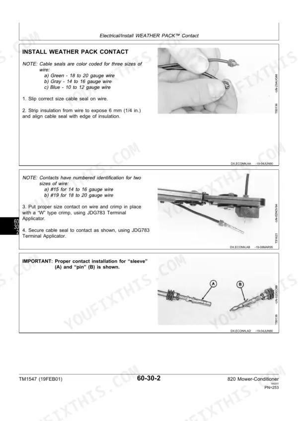
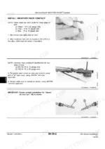
Yes, one. Page 267 shows the warning light wiring from the tractor's seven-terminal outlet to the left and right warning lights, with wire numbers and colors. The rest of the short electrical group covers Weather Pack connector repair on pages 265 and 266.







Reviews
There are no reviews yet.