Part of the John Deere Repair Manuals.
This is the Operation and Test technical manual for John Deere 8120T, 8220T, 8320T, 8420T and 8520T track tractors (). It is the diagnostic half of the factory library: service codes, observable symptoms, system diagnosis, and the actual test specs a tech needs at the connector. You get the seven-step electrical test procedure, full wiring schematics, powershift transmission checks, hydraulic operational tests with theory of operation, and the ACU address tables with real voltage windows - hand throttle 0.50-2.50 volts full back, SCV lever positions, shift lever bit codes. AMS coverage includes GreenStar, AutoTrac and JDLink diagnostics. These tractors talk through their controllers; this book is how you listen. Pair it with TM1971 when it is time to pull things apart.
What's Inside This John Deere 8120T-8520T Manual
| System | Pages | Key Topics |
|---|---|---|
| General | 8-85 | Safety Procedures, General References, Bolt and Cap Screw Torque Values, Glossary of Terms, JIC Hydraulic Symbols |
| Service Codes | 86-680 | PCU Code Diagnostics, CCU Code Diagnostics, ACU Code Diagnostics, SCU Code Diagnostics, SSU Code Diagnostics, ATC Code Diagnostics |
| Observable Symptoms | 681-840 | Electrical Symptoms, Operator Station Symptoms, Steering Symptoms, Hitch Symptoms, Heating Ventilation and Air Conditioning Symptoms |
| System Diagnosis | 841-909 | Steering and Brakes System, Transmission System, Hydraulic System, Climatrak |
| Engine | 910-931 | Operational Checks, Tests and Adjustments, Theory of Operation, Schematics and Diagrams |
| Fuel and Air | 932-945 | Fuel System Theory of Operation, Air Intake Theory of Operation |
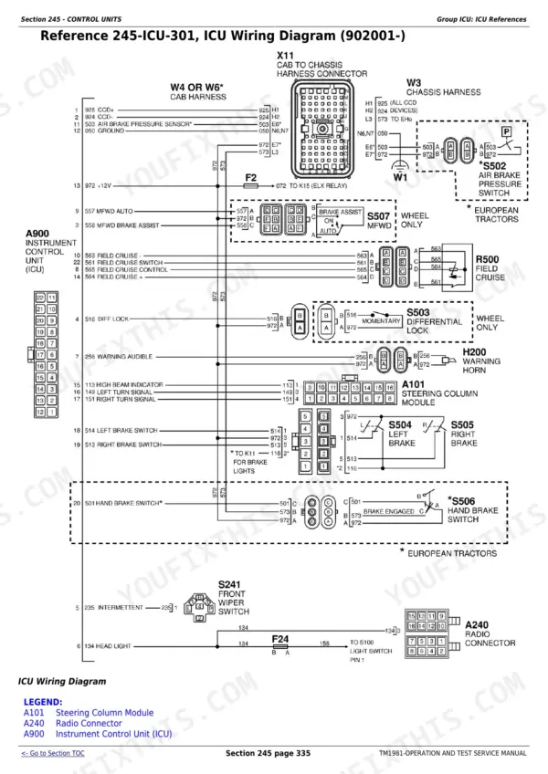
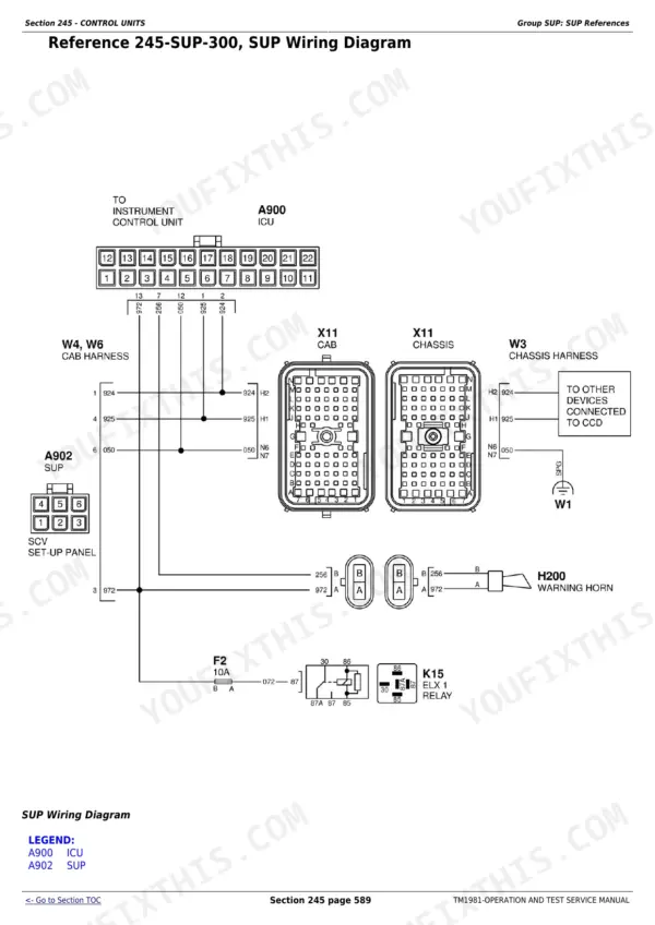
| Electrical | 946-1121 | Wiring Diagrams and Schematics, Electrical Schematic Symbols, Circuit Types and Malfunctions, Seven-Step Electrical Test Procedure, Using a Probe Light and Digital Multimeter |
| Control Units | 1122-1714 | CCU References, PCU References, ACU References, SCU References, SSU References, HCU References, Codes and Addresses |
| Transmission | 2084-2208 | Powershift Transmission, Operational Checks, Tests and Adjustments, Theory of Operation |
| Drive Systems | 2209-2226 | Theory of Operation, Tests and Adjustments |
| Steering and Brakes | 2227-2284 | Preliminary Checks, Operational Checks, Theory of Operation, Schematics and Diagrams, Tests and Adjustments |
| Hydraulics | 2285-2412 | Preliminary Checks, Operational Checks, Hydraulic Theory of Operation, Pressure and Flow Tests, Selective Control Valve Tests |
| Operator Station | 2413-2580 | Preliminary Checks, Operational Checks, Theory of Operation, Tests and Adjustments |
| Tools | 2581-2607 | Fabricated Tools, Test Kits |
| Ag Management Solutions (AMS) | 1715-2083 | GreenStar Diagnostics, JDLink Diagnostics, AutoTrac Diagnostics, Field DOC Operation and Tests, GPS Position and StarFire Receiver Tests |
Quick Reference Specifications
| Specification | Value | Page |
|---|---|---|
| ACU Address 03 | ||
| Hand Throttle Voltage (Full Back) | 0.50-2.50 Volts (ACU Address 03) | p. 86 |
| Hand Throttle Voltage (Full Forward) | 2.50-4.50 Volts (ACU Address 03) | p. 86 |
| Hand Throttle Voltage Range (Prior to Software Version 30) | >1.78 Volts (ACU Address 03) | p. 86 |
| Hand Throttle Voltage Range (Software Version 30 and Above) | >1.58 Volts (ACU Address 03) | p. 86 |
| ACU Address 08 | ||
| Rear Hitch Load / Depth Control Voltage (CCW) | 0.50-2.50 Volts (ACU Address 08) | p. 86 |
| Rear Hitch Load / Depth Control Voltage (CW) | 2.50-4.50 Volts (ACU Address 08) | p. 86 |
| Rear Hitch Load / Depth Control Voltage Range (Prior to Software Version 30) | >1.78 Volts (ACU Address 08) | p. 86 |
| Rear Hitch Load / Depth Control Voltage Range (Software Version 30 and Above) | >1.58 Volts (ACU Address 08) | p. 86 |
| ACU Address 09 | ||
| Rear Hitch Lever Control Voltage (Raise) | 0.50-2.50 Volts (ACU Address 09) | p. 86 |
| Rear Hitch Lever Control Voltage (Lower) | 2.50-4.50 Volts (ACU Address 09) | p. 86 |
| Rear Hitch Lever Control Voltage Range (Prior to Software Version 30) | >1.78 Volts (ACU Address 09) | p. 86 |
| Rear Hitch Lever Control Voltage Range (Software Version 30 and Above) | >1.58 Volts (ACU Address 09) | p. 86 |
| ACU Address 10 | ||
| Rear Hitch Raise Limit Control Voltage (Limited Raise) | 0.50-2.50 Volts (ACU Address 10) | p. 86 |
| Rear Hitch Raise Limit Control Voltage (Maximum Raise) | 2.500-4.50 Volts (ACU Address 10) | p. 86 |
| Rear Hitch Raise Limit Control Voltage Range (Prior to Software Version 30) | >1.78 Volts (ACU Address 10) | p. 86 |
| Rear Hitch Raise Limit Control Voltage Range (Software Version 30 and Above) | >1.58 Volts (ACU Address 10) | p. 86 |
| ACU Address 11 | ||
| Rear Hitch Rate-of-Drop Control Voltage Range (Prior to Software Version 30) | >1.78 Volts (ACU Address 11) | p. 86 |
| Rear Hitch Rate-of-Drop Control Voltage Range (Software Version 30 and Above) | >1.58 Volts (ACU Address 11) | p. 86 |
| All Models | ||
| SCV Control Voltage and Switch Status (Float) | 0.2.0-1.2.0 (ACU Address 12); 0.2.0-1.2.0 (ACU Address 13); 0.2.0-1.2.0 (ACU Address 14); 0.2.0-1.2.0 (ACU Address 15); 0.2.0-1.2.0 (ACU Address 16) | p. 86 |
| SCV Control Voltage and Switch Status (Retract / Forward Detent) | 1.2.1-1.8.1 (ACU Address 13); 1.2.1-1.8.1 (ACU Address 14); 1.2.1-1.8.1 (ACU Address 15); 1.2.1-1.8.1 (ACU Address 16) | p. 87 |
John Deere 8120T-8520T Common Problems This Manual Covers
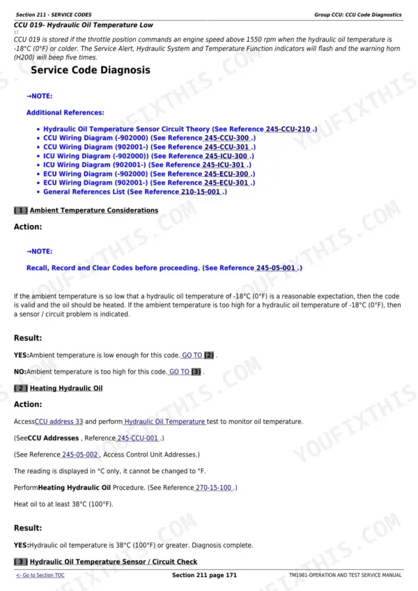
Hydraulics weak or dead, with slow SCVs and oil running hot while code CCU 019 is logged
The Hydraulics section runs operational checks in order: oil level, hydraulic filters, charge pump suction screen, oil cooler air passages, then pressure tests to isolate a high-pressure internal leak. CCU 019 hydraulic oil temperature diagnosis is on page 256, with theory of operation and schematics to trace the circuit.
Manual Section: Hydraulics - Operational Checks, Tests and Adjustments p. 811Transmission will not shift right, sets PCU codes, or refuses calibration
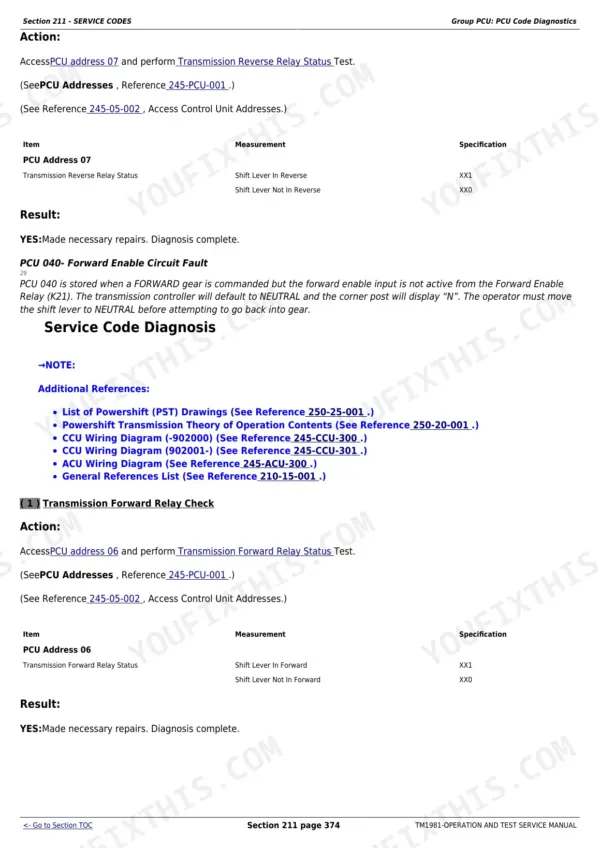
Section 211 decodes the fault, then the Transmission section takes over with calibration and clutch tests. PCU 040-044 procedures on page 459 check clutch valve solenoids, armrest shifter circuits and the ground speed sensor before you condemn the controller. The ACU address 04-06 shift lever bit tables on page 86 verify lever inputs directly.
Manual Section: Section 211 - Service Codes / Transmission Tests and Adjustments p. 843Steering drifts while moving down the road or in the field
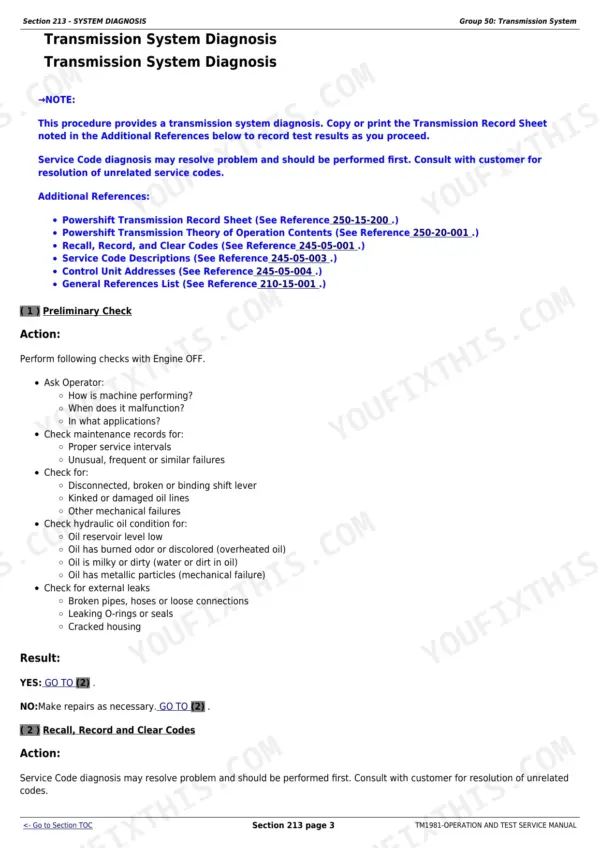
Section 260 covers steering and brakes diagnosis for the differential steer system. You test solenoid resistance, speed sensor inputs and steering valve response against spec instead of swapping parts blind. Section 213 system diagnosis helps separate a hydraulic cause from an electrical one before you start.
Manual Section: Section 260 - Steering and Brakes p. 459Starter will not crank, or intermittent armrest power kills the transmission (ACU 041)
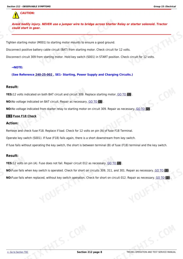
The Electrical section's seven-step test procedure walks the start circuit from battery through interlocks to the starter with a multimeter, using the full wiring schematics. For ACU 041 and other armrest faults, Section 245 control unit diagnosis plus the connector checks find the loose plug that causes most of these complaints.
Manual Section: Electrical - Seven-Step Test Procedure / Section 245 - Control Units p. 1128Frequently Asked Questions
My 8420T is throwing codes on the display. Does this manual tell me what they mean and how to work through them?
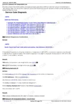
Yes, that is the core of the book. Section 211 covers service codes, and the code procedure starting on page 377 walks you through reading, interpreting and clearing them by controller: ACU codes for the armrest, PCU for the powershift, CCU for chassis. For example, PCU 040-044 transmission codes are laid out on page 459 with the test steps to run before you replace anything. p. 377
The transmission shows PCU 040 with the transmission not calibrated and shifts rough. Is the calibration procedure in here?
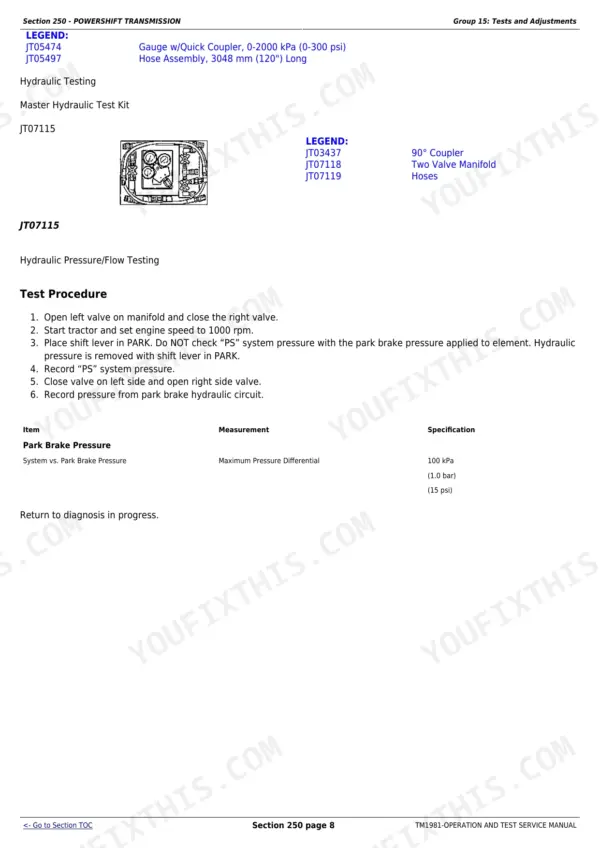
Yes. The Transmission section covers powershift operational checks, tests and adjustments, including calibration and the follow-up tests when it will not take a calibration - shifter circuit faults, clutch valve solenoids, ground speed sensor and wiring. On these tractors an uncalibrated transmission is a no-go condition, so this procedure gets used a lot. p. 459
Hitch will not raise, or cycles up and down on its own. Will this manual get me to the cause?
It will. The ACU address tables on page 86 give you exact voltage ranges for the hitch lever, load/depth knob, raise limit and rate-of-drop controls, so you can check each input with a multimeter. Code ACU 049 (raise/lower rocker on during start) is covered on page 1126, and ACU 053-57 point you at open or shorted hitch inputs. p. 256
Is this the manual for tearing into the transmission or replacing seals?
No. This is the Operation and Test volume: diagnosis, schematics, operational checks and test specifications. It tells you which component failed and proves it with a measurement. Component removal, disassembly and rebuild live in the separate repair manual TM1971. Most techs end up wanting both, but if you are chasing electrical or hydraulic gremlins, this is the one you will open first.
I am not an electrician. Can I actually use the wiring diagrams in here?
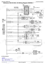
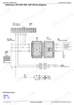
Yes, and the Electrical section assumes you might not be. It explains schematic symbols, circuit types and common malfunctions, then teaches a seven-step test procedure using a probe light and a digital multimeter. It even specs wire gauge current draw limits (page 59) so you know what a healthy circuit should carry. Work the steps in order and the diagrams stop looking like spaghetti. p. 1456