
Part of the John Deere Repair Manuals.
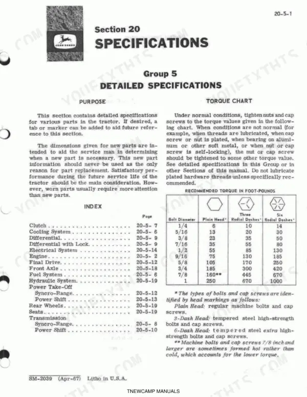
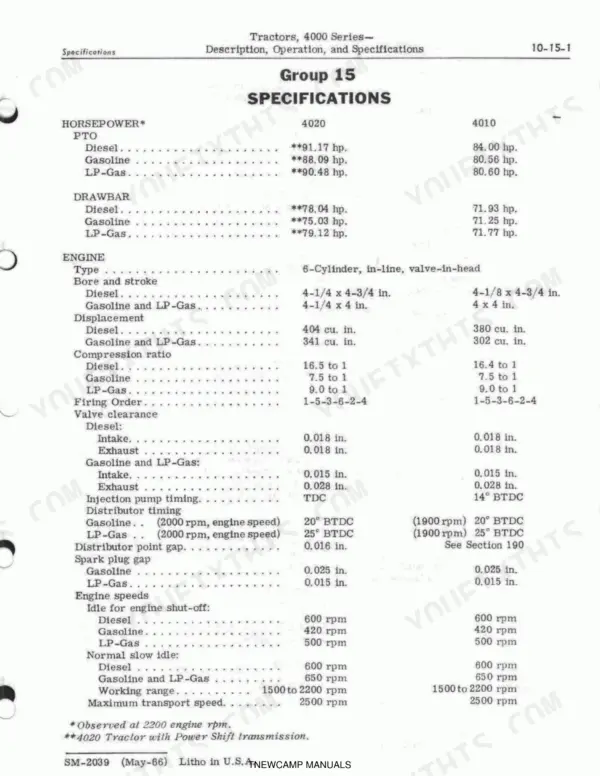
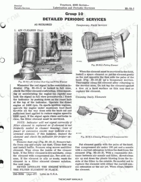
This 746-page John Deere 4010, 4020, 4000 Series Tractors Service Manual puts the complete factory teardown for these Syncro-Range and Power Shift tractors in your hands. Inside you'll find full wiring diagrams for the charging circuit and starter system, hydraulic schematics covering the pump, power steering, and rockshaft circuits, plus a dedicated troubleshooting section for when the tractor just won't cooperate. Your battery spec reads 12-volt, 78-plate, 75-ampere-hour, and the oil-bath air cleaner takes 4-3/4 U.S. pints on diesel models versus 2-3/4 pints on gasoline and LP-Gas versions, straight from the factory page, not a forum guess. No more flipping through a warped shop copy trying to find the differential preload numbers. Every section from Basic Engine to Special Service Tools is bookmarked and keyword-searchable, so you can jump straight to Power Brakes or Final Drive without hunting through 746 pages by hand.
Other edition of this manual
What's Inside This John Deere 4010 & 4020 Manual
| System | Pages | Key Topics |
|---|---|---|
| Description, Operation & Specifications | 5-30 | Engine, Crankcase Ventilating System, Clutch, Fuel System, Electrical System, Hydraulic System |
| Specifications | 31-52 | Engine, Clutch, Transmission, Hydraulic System, Electrical System, Final Drive |
| Lubrication | 53-72 | Engine Lubricating Oils, Greases, Air Cleaner, Fuel Filters, Engine Crankcase, Transmission-Hydraulic System |
| Engine Tune-Up | 73-104 | Air Intake System, Engine, Ignition System, Fuel Systems, Cooling System, Charging Circuit |
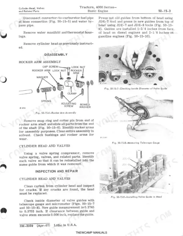
| Basic Engine | 105-144 | Engine Components, Cylinder Head, Valves, Cylinder Block, Pistons, Crankshaft |
| Engine Lubrication System | 145-154 | Oil Pump, Oil Filter Assembly, Diesel Engine Oil Cooler |
| Cooling System | 155-164 | Water Manifold, Radiator, Thermostat Housings, Water Pump, Fan, Radiator Cap, Fan Hub, Thermostats |
| Gasoline and Lp-Gas Fuel Systems | 165-218 | Fuel Tank, Fuel Pump, Pipes, Gasoline Carburetor, LP-Gas Fuel System |
| Diesel Fuel System | 219-264 | Fuel Tank, Fuel Pump, Injection Pump, Injection Nozzles, Air Cleaner |
| Syncro-Range Transmission and PTO Clutches | 265-284 | Transmission Clutch, PTO Clutch, Clutch Shafts, Clutch Controls, Clutch Assemblies |
| Engine Disconnect Clutch | 285-292 | Clutch Controls, Release Bearing Assembly, Control Lever Assembly |
| Syncro-Range Transmission | 293-322 | Transmission Drive Shaft, Countershaft, Differential Drive Shaft, Shifter Controls, Shifters |
| Power Shift Transmission | 323-404 | Clutch Pack, Planetary Pack, Transmission Control System, Transmission Testing, Reduction Gear Train |
| Differential | 405-420 | Differential Lock, Servicing the Differential, Inspection and Repair, Preload Adjustment, Backlash Adjustment |
| Final Drive System | 421-432 | Planet Pinion Carrier, Rear Axle, Final Drive Gear Housing |
| Syncro-Range PTO and Belt Pulley | 433-450 | Power Take-Off, Belt Pulley, Servicing the PTO, PTO Shaft, Shifter Collars, Belt Pulley Assembly |
| Power Shift PTO | 451-460 | PTO Shaft, PTO Clutch, Control Valve, Brake Piston, Idler Gear, Gear Train |
| Sheet Metal | 461-468 | Cowl, Hood, Grille, Side Panels, Fenders, Platform |
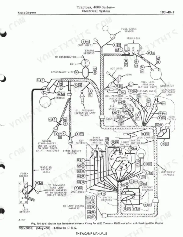
| Electrical System | 469-536 | Generator, Regulator, Battery, Starter, Ignition System, Wiring Diagrams |
| Seats | 537-546 | Seat Cushion, Seat Back Cushion, Suspension System, Latch Handle, Position Selector Lever, Rollers |
| Front Axle Equipment | 547-556 | Spindle Extension, Sector Gears, Knuckles, Wheel Spindles, Thrust Washers, Pivot Pins |
| Wheels Tires and Weights | 557-566 | Front Wheels, Rear Wheels, Tires, Weights |
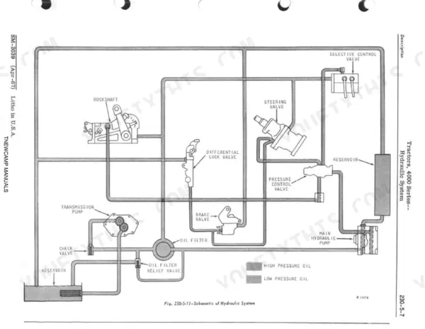
| Hydraulic System | 567-588 | Main Hydraulic Pump, Hydraulic Oil Cooler, Power Steering, Power Brakes, Selective Control Valves, Remote Hydraulic Cylinders, Rockshaft |
| Hydraulic Pumps | 589-606 | Transmission Pump (Syncro-Range), Transmission Pump (Power Shift), Main Hydraulic Pump, Stroke Control Valves, Pump Shaft, Drive Disks and Coupler |
| Power Steering | 607-634 | Steering Valve, Steering Motor, Valve Operating Shaft, Piston Rod, Control Valves, Oil Seal |
| Power Brakes | 635-646 | Operating Valves, Brake Valve Plunger, Brake Disk, Brake Cylinders, Brake Pressure Plates, Bleed Screws |
| Rockshaft, 3-Point Hitch,And Quick Coupler | 647-678 | Rockshaft, 3-Point Hitch, Quik-Coupler, Selector Lever, Control Lever, Throttle Valve |
| Remote Cylinder Selective Control Valve | 679-690 | Control Valve, Operating Arm, Operating Cams |
| Breakaway Couplers and Remote Cylinders | 691-700 | Breakaway Couplers, Remote Cylinders, Breakaway Coupler Pipes, Breakaway Coupler Receptacle, Breakaway Coupler Body, Piston Rod, Stop Rod, Stop Valve |
| Drawbar Assembly | 701-704 | Row-Crop and Standard Drawbars, Wide Swing, 4010 Hi-Crop Drawbar |
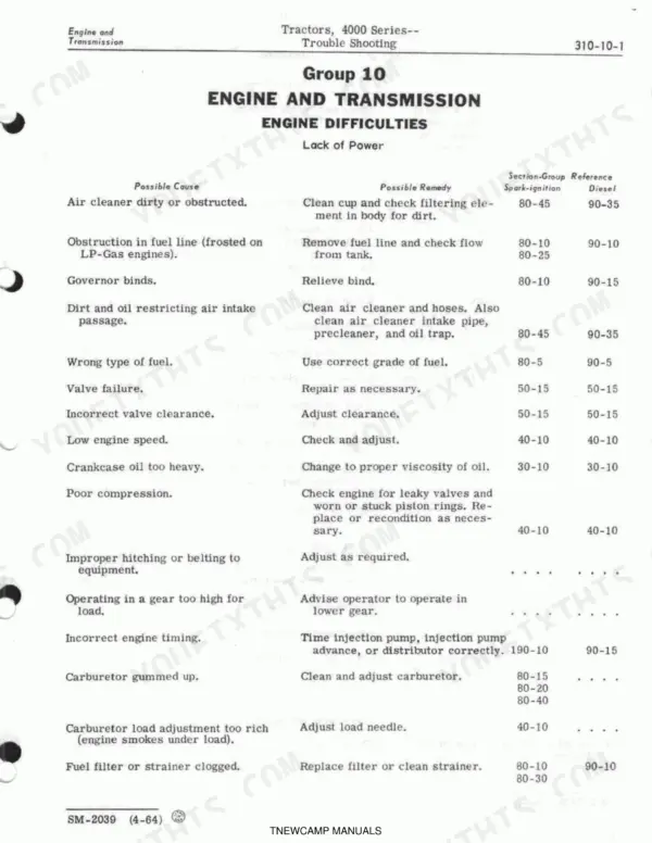
| Trouble Shooting | 705-730 | Brakes, Clutch (Syncro-Range), Differential Lock, Electrical System, Engine, Generator, Hydraulic Pump, Hydraulic System |
| Special Service Tools | 731-742 | Engine, Tractor Splitting, Compression, Engine Oil Pressure, Piston Ring, Counterboring, Rocker Arm, Water Pump Bearing |
Quick Reference Specifications
| Specification | Value | Page |
|---|---|---|
| Model numbers for main hydraulic pump | Carried by the distributor | p. 6 |
| Serial number location for generator | On the generator mounting pad on the front right side of the cylinder block | p. 6 |
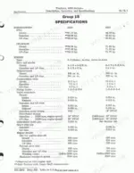
| Battery | 12-volt, 78-plate, 75-ampere-hour | p. 26 |
| Air cleaner (oil-bath) Diesel | 4-3/4 U.S. pints | p. 26 |
| Air cleaner (oil-bath) Gasoline and LP-Gas | 2-3/4 U.S. pints | p. 26 |
| Hydraulic pump drive coupler cap screws (with wire) | 25 ft-lbs. | p. 36 |
| Fan belt tension (deflected in 1 in.) | 25 lbs | p. 36 |
| Fan blade-to-hub cap screw torque | 35 ft-lbs. | p. 36 |
| I.D. of housing at O-ring for pump shaft | 1.385 to 1.396 in. | p. 50 |
| O.D. detent and centering cam shaft O-ring groove | 0.248 to 0.252 in. | p. 52 |
| Air cleaner (dry type) Clean filter element | Clean filter element | p. 54 |
| Fuel filters Replace both filters | Replace both filters | p. 54 |
John Deere 4010 & 4020 Common Problems This Manual Covers
John Deere 4020 hydraulic pump losing pressure under load, rockshaft and 3-point hitch won't lift
Check the troubleshooting chart on page 721 for oil not reaching the pump: verify the clutch is engaged and the transmission pump is functioning. Test main pump standby pressure with a gauge at the test port; page 585 specifies 2200 to 2300 psi. If pressure reads low, check for internal leakage against the page 588 limit of 1/2 pint per minute per function, and inspect valve seats and O-rings for wear.
Manual Section: Hydraulic System p. 585Generator producing no output, noisy whine, or excessive charge rate at full throttle
Inspect the brushes first; page 492 sets spring tension at 24 to 32 ounces, and page 503 puts the wear limit at 5/16 inch, so replace any brush shorter than that. Check the cutout relay air gap on page 496, which should measure 0.020 inch. Clean the cutout relay contact points per page 720 if internal resistance is high, then retest output with the engine at operating rpm.
Manual Section: Electrical System p. 492Engine running rough with low power output, hesitation, and high fuel consumption under load
Work through the troubleshooting procedures starting on page 707, which cover lack of power, irregular running, and misfires. On gasoline engines, check spark plug gap against the 0.025 inch spec on page 44 and regap or replace fouled plugs. On diesel engines, verify intake valve clearance is set to 0.018 inch per page 25. Also pull and clean the air cleaner element, since a clogged element chokes airflow and richens the mixture.
Manual Section: Trouble Shooting p. 707Battery draining water fast or won't hold a charge overnight, dim lights on startup
Pull each cell cap and test with a hydrometer; a good charged battery reads under 0.05 volt difference between cells per the spec on page 47. Confirm the battery matches the page 509 spec of 12-volt, 78-plate, 75 ampere-hour rating and isn't a mismatched replacement. If cells test low across the board, charge or replace per the direction on page 718, and check the regulator's cutout relay air gap (0.020 inch, page 496), since a bad setting will overcharge and boil electrolyte out.
Manual Section: Electrical System p. 509Power steering leaks oil and feels spongy or hard to turn at full lock
Turn the wheel fully to the right first; leakage here points to bad left-hand valves, balls, or seats per page 722. Turning left and finding leakage instead means the right-hand valves or seats are worn. Check the steering motor oil hose tube fitting for defective piston O-rings as noted on page 723, and inspect the steering valve piston rod O-ring in the cylinder cover if oil weeps from the housing during turns.
Manual Section: Trouble Shooting p. 722Frequently Asked Questions
What are the torque specifications for the connecting rod bearings on a John Deere 4010 engine?
For a John Deere 4010 engine, the connecting rod bearings should be torqued to 85-95 ft-lbs for gasoline tractors and 100-110 ft-lbs for diesel tractors. This specification is crucial for proper engine assembly and operation. p. 36
How do you adjust the Power Shift transmission on a John Deere 4020?
To adjust the Power Shift transmission speed-of-shift on a John Deere 4020, stop the engine and remove the adjusting screw plug (Fig. 10-10-17) at the bottom of the valve housing. Turn the adjusting screw in clockwise to slow down shifting or out to speed it up, making adjustments in one-half turn increments and testing after each adjustment. p. 19
What are the torque specifications for the flywheel bolts on a John Deere 4010?
The flywheel-to-crankshaft cap screws on a John Deere 4010 engine should be torqued to 85 ft-lbs. This ensures the flywheel is securely attached to the crankshaft flange. p. 36
How do you fix engine stalling on a John Deere 4010 tractor?
If a John Deere 4010 engine starts but will not continue running (stalling), possible remedies include installing a new key switch, replacing the ignition resistance wire, installing new wiring, replacing the coil or condenser, cleaning or replacing pitted/burned breaker points, or adjusting the carburetor idle needle. The specific remedy depends on the identified cause. p. 713
What exactly do I receive with this John Deere 4010 Service Manual?
Instant PDF download. You get the full 746-page searchable Service Manual immediately after payment. Open it on your laptop, tablet, or phone right in the shop.
Does this John Deere 4010 manual allow printing?
Absolutely. No DRM or copy protection. Print the whole manual or just the pages you need. Any home or office printer works.
Are wiring diagrams part of this John Deere 4010 Service Manual?
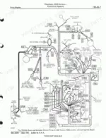
Complete wiring diagrams are included, covering all electrical circuits, harness routing, and connector pinouts for the John Deere 4010, 4020, 4000 Series Tractors.








Reviews
There are no reviews yet.