Part of the John Deere Repair Manuals.
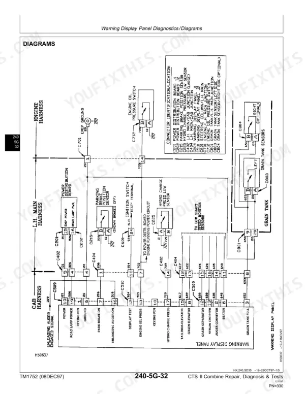
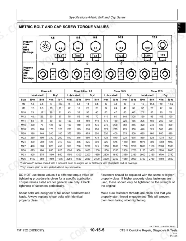
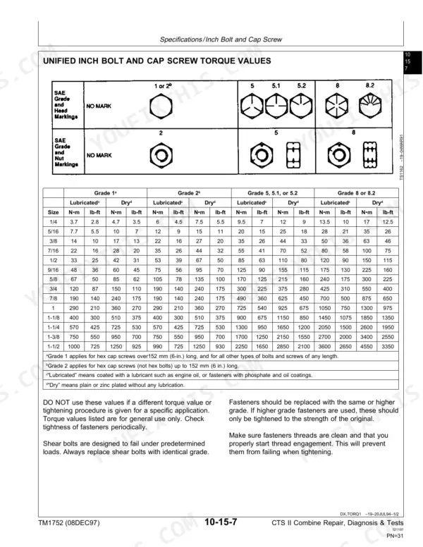
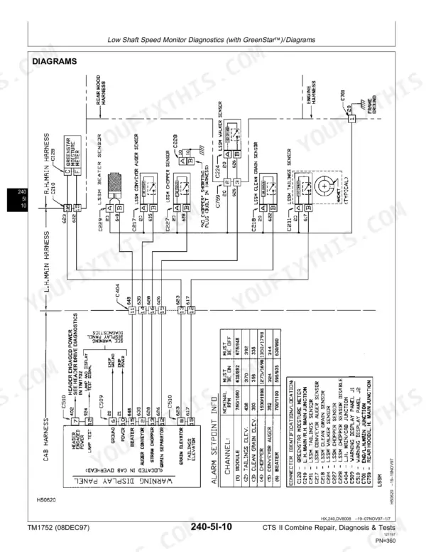
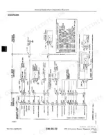
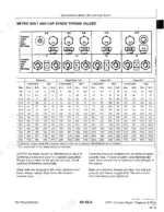
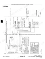
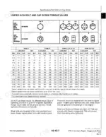
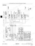
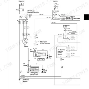
Rebuilding the beaters, shaker pan, chaffer and sieve on a John Deere CTS II combine is where TM1752 earns its 444 pages, down to the tine separator module and gearboxes. This John Deere CTS II technical manual PDF also gives you wiring diagrams for the warning display panel, low shaft speed monitor, HarvesTrak and lighting system, plus a key to electrical schematic symbols. Grain tank extensions and the hinged corner and main panels get their own repair section, while metric and inch bolt and cap screw torque charts back up the fastener work. Fill the engine crankcase to 28.5 L (30 U.S. qts.) with the filter; the fuel tank takes 530 L (140 gal.). For a thermostat replacement, order two, each rated 82°C (180°F). Bookmarks take you straight to the separator chapter, and the text layer lets you search any circuit name, so your beater and sieve rebuild goes back together to the book's own torque values.
What's Inside This John Deere CTS II Manual
| System | Pages | Key Topics |
|---|---|---|
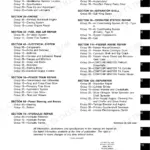
| General | 7-32 | Safety, Combine Identification Number, Engine Serial Number, Engine Gearcase, Hydrostatic Drive Unit Pump, Hydrostatic Drive Unit Motor, Left Cam Lobe Four-Wheel Drive Motor, Right Cam Lobe Four-Wheel Drive Motor, Transmission, Dimension Reference Points, Dimensions, Feeder House Reverser Gearcase, Brakes, Metric Bolt and Cap Screw Torque Values, Unified Inch Bolt and Cap Screw Torque Values |
| Beaters | 35-122 | Tine Separator System Diagram, Serated Beater Drive Gearbox, Serated Beater and Shaft, Stripper Beater, Serated Beater Cover |
| Shaker Pan, Chaffer, Sieve and Frames | 123-144 | Shaker Pan, Chaffer, Sieve and Frames, Shaker Pan Location Drawing, Chaffer Frame Location Drawing, Sieve Frame Location Drawing, Precleaning Chaffer Location Drawing |
| Tine Separator Module | 145-186 | Tine Module Backbone Wearout, Module Frame and Covers, Remove Front Feed Section Assembly, Module Grate Assembly, Module Crank-Out System |
| Tine Separators | 187-212 | Tine Separator Front Bearings and Lube Lines, Remove Tine Separators, Repair Tine Separators, Replace Tines, Replace Discharge Paddles |
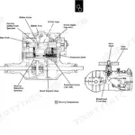
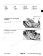
| Engine Gearcase to Module Drives | 213-232 | Engine Gearbox to Module Drives, Disassemble Module Drive, Assemble Module Drive |
| Tine Separator Gearboxes | 233-262 | Disassemble and Repair Module Drive, Remove Module Drive Gearbox, Assemble Module Drive Gearbox, Install Module Drive Gearbox |
| Straw Chopper, Straw Spreader and Chaff Spreader | 263-276 | Straw Chopper, Straw Spreader and Chaff Spreader, Straw Chopper Drives, Remove and Install Straw Chopper, Straw Spreader Drive |
| Grain Tank and Unloading System Repair | 277-282 | Grain Tank Extensions, Hinged Corner Panels, Hinged Main Panels, Grain Tank Capacity |
| Electrical Diagnostics and Tests | 283-444 | Warning Display Panel, Low Shaft Speed Monitor, HarvesTrak, Lighting System, Electrical Schematic Symbols |
Quick Reference Specifications
| Specification | Value | Page |
|---|---|---|
| Thermostats (Two) | 82°C (180°F) | p. 25 |
| Engine crankcase (with filter) capacity | 28.5L (30 U.S. qts.) | p. 26 |
| Engine Brake Horsepower | 205 rated with 230 kW boost (275 with 308 hp boost) | p. 25 |
| Engine Displacement | 8.1L (496 cu. in.) | p. 25 |
| Fuel Tank Capacity | 530L (140 gal.) | p. 26 |
| Hydraulic/Hydrostatic Reservoir Capacity | 34L (36 U.S. qts.) | p. 26 |
| Serated Beater T.I.R. Clearance | 0.05 mm (0.002 in.) | p. 36 |
| Shaker Pan Approximate Weight | 71 kg (157 lb) | p. 123 |
| Tine Separator Module Approximate Weight | 1023 kg (2250 lb) | p. 146 |
| Gearbox Bevel Gear Backlash | 0.20-0.40 mm (0.008-0.016 in.) | p. 233 |
| Drive Gearbox Input Bearings Endplay | 0.05-0.15 mm (0.002-0.006 in.) | p. 233 |
| Straw Chopper Approximate Weight | 159 kg (350 lb) | p. 263 |
John Deere CTS II Common Problems This Manual Covers
John Deere CTS II low shaft speed monitor warning light and audible alarm stay on
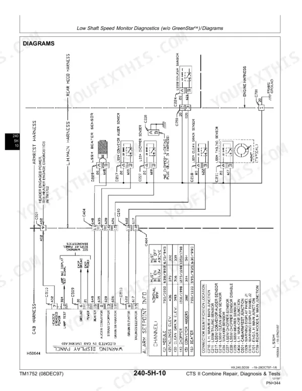
Stop the engine, remove the key, and disconnect the battery ground cable (-) before adjusting any monitor wiring, per page 17. Work through the Low Shaft Speed Monitor diagnostic flowcharts; page 339 explains that the light and alarm stay on until the low shaft speed is corrected. Use the component location section to find parts on the flagged shaft, then trace the circuit on the wiring diagram.
Manual Section: Low Shaft Speed Monitor Diagnostics p. 339Warning display panel light comes on but the audible warning buzzer stays silent
Check whether a higher priority (lower number) warning is active; per page 306, that blocks the lower audible warning. Clear that condition first, then run the specific warning light diagnostics in Warning Display Panel Diagnostics, which also cover calibration. For an audible priority 1 warning, verify the buzzer beeps continuously four seconds after the sensor indicates a problem (page 312).
Manual Section: Warning Display Panel Diagnostics p. 306Serated beater shaft shows wear or excessive runout after removal from the combine
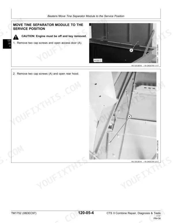
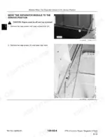
Shut the engine off and remove the key, then move the tine separator module to the service position as shown on page 38. Support the serated beater, roughly 86 kg (190 lb), so it cannot drop when the shaft comes out (page 74). Inspect the shaft for wear and measure runout against 0.05 mm (0.002 in.). Reinstall from the right-hand side, aligning the key seat with the beater hub (page 75).
Manual Section: Separator Repair p. 74Tine separator drive gearbox bevel gear backlash or input bearing endplay out of specification
Block up the tine separators at the grates before pulling the gearboxes so they cannot drop (page 196); each gearbox weighs about 29 kg (64 lb). Save the shim washers from the gearbox top and reinstall them in the same location, using the number stamped above the gearbox (page 241). Measure bevel gear backlash against 0.20-0.40 mm (0.008-0.016 in.) and input bearing endplay against 0.05-0.15 mm (0.002-0.006 in.) per page 233.
Manual Section: Separator Repair p. 233Chaffer, sieve, or precleaner elements damaged and needing removal from the frames for repair
Disconnect the battery ground strap, remove the key, and hang a CAUTION DO NOT OPERATE tag in the operator's station so the engine cannot be started (page 133). Leave the shaker pan in place if only chaffer and sieve elements come out; otherwise remove the 71 kg (157 lb) pan (page 134). Install frames and shaker pan with capscrews and nuts left untightened, as pages 140 through 142 direct.
Manual Section: Shaker Pan, Chaffer, Sieve and Frames p. 133Road transport warning lights flash at the wrong rate when a turn signal is selected
Move the light switch to the first position and verify the four amber grain tank lights flash at 60 FPM, switching to 90 FPM on the side selected at the turn signal switch (page 382). If not, follow the Lighting System Diagnostics flowcharts and check connector C239, the left side road transport warning light connector (page 388).
Manual Section: Lighting System Diagnostics p. 382Frequently Asked Questions
What are the torque specifications for the John Deere CTS II separator, engine, and drive components?
The manual provides specific torque values for various components. For example, the module side rail bolts require 191 N•m (141 lb-ft), and the module to separator bolts require 77 N•m (57 lb-ft). Beater wing cap screws should be torqued to 45 N•m (35 lb-ft). p. 36
What are the replacement specifications for air-cleaner filter elements on the John Deere CTS II?
The engine air cleaner is a dry type with a safety element. The manual specifies that you should clean or replace the primary filter element and replace the safety air filter element when the warning light is on. p. 310
What is the capacity of the grain tank on the CTS II combine?
The grain tank capacity for the CTS II combine is 8,457 liters, which is equivalent to 240 bushels. p. 26
What is the correct procedure for checking the gear backlash on the module drive gearbox?
To check the gear backlash, use a dial indicator. The backlash must be between 0.20 and 0.40 mm (0.008 to 0.016 in.). If adjustment is needed, use shims on the right-hand end to achieve the proper backlash. p. 255
What is the required oil capacity for the tine separator gearbox on the John Deere CTS II?
The approximate capacity for the tine separator gearbox is 2.0 liters (2.1 quarts) of 80 W/90 gear lubricant oil. p. 233
How is this John Deere CTS II Technical Manual delivered?
All 444 pages arrive as one searchable PDF at checkout. Read it at the desk, then take the phone out to the machine.
Can I print specific sections of this John Deere CTS II Technical Manual?
Yes. Print the pages you need for the job in your own shop, and bin them when they get greasy.