
Part of the John Deere Repair Manuals.
Looking for a John Deere 40 technical manual PDF? This 73-page Technical Manual (OEM #TM1593) covers the full line of John Deere hydraulic attachments: the 8A, 10, and 10A backhoes, the 40, 44, 60, 70, and 70A loaders, plus the 51, 52, 67, 365, 375, 380, 380A, and 390 tillers, blades, and hydraulic dump units. Inside you get hydraulic schematics with theory of operation for every circuit, troubleshooting charts for backhoe and loader systems, and a full run of cylinder repair procedures from disassembly to seal replacement. Torque tables span unified inch, metric, and O-ring boss fitting values. Check lift cylinder drop rate against the 10.4 mm/min limit, then set the lift cylinder lock nut to 272 N-m (200 lb-ft). No more chasing hydraulic leaks on guesswork. Bookmarked with a live text layer; search a spec, jump to it, and get your attachment back on the tractor.
What's Inside This John Deere 8A–390 Hydraulic Attachments Manual
| System | Pages | Key Topics |
|---|---|---|
| Introduction | 2 | Table of Contents, Specifications, Component Location, System Schematic, Theory of Operation, Troubleshooting Chart |
| Safety | 3-7 | Safety Information, Signal Words, Safety Signs, Fire Prevention, High-Pressure Fluid Lines, Protective Clothing |
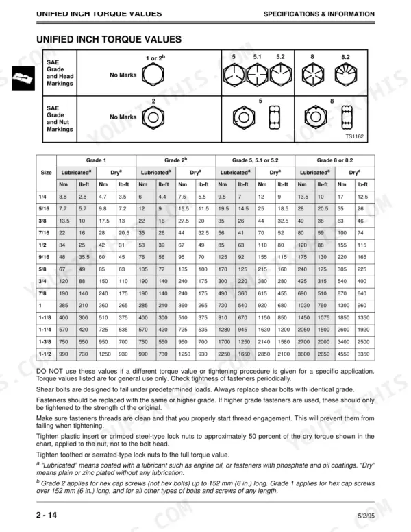
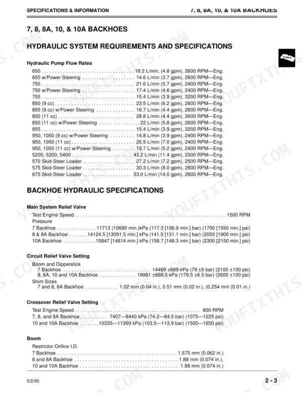
| Specifications & Information | 8-23 | Backhoe Hydraulic Specifications, Loader Capacities, Fitting Torque Values, Unified Inch Torque Values, Metric Torque Values, Lubricants |
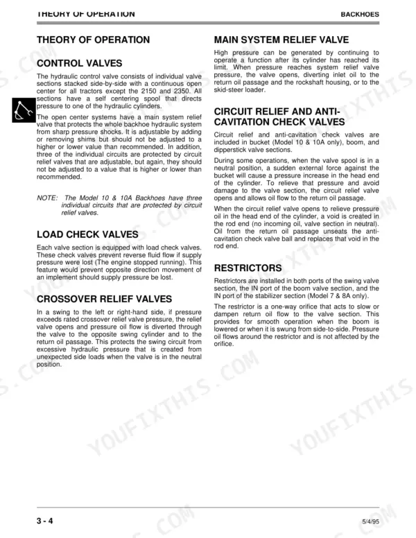
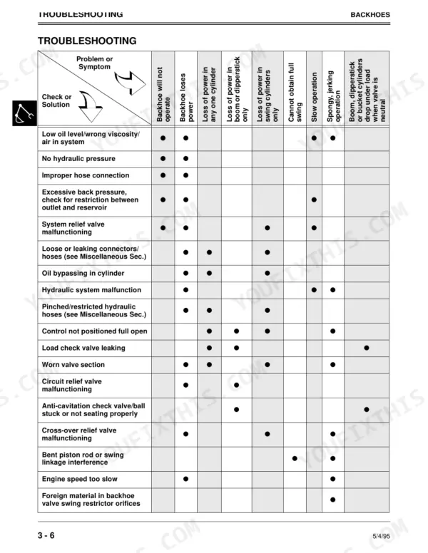
| Backhoes | 24-49 | Component Location, Theory of Operation, Troubleshooting, Diagnostics, Tests and Adjustments, Cylinder Repair |
| Loader | 50-57 | Troubleshooting, Theory of Operation, Cylinder Repair, Control Valve, Hydraulic Pump, Loader Restrictors |
| Tiller | 58-63 | Hydraulic Pump, Hydraulic Motor, Disassembly, Assembly |
| Blades | 64-65 | Angle Cylinder, Lift Cylinder |
| Hydraulic Dump | 66-67 | Cylinder Repair, Disassembly, Assembly |
| Miscellaneous | 68-71 | Hoses, Fittings, Hose Selection, Hose Failures, Hose Routing, Hose Installation |
Quick Reference Specifications
| Specification | Value | Page |
|---|---|---|
| 60, 70, 70A | ||
| Lift cylinder drop rate (maximum acceptable limit from transport position) | 10.4 mm/min (.41 in./min) | p. 18 |
| Bucket cylinder drop rate (maximum acceptable limit from rollback position) | 13 mm/min (.51 in./min) | p. 18 |
| 655, 670, 770, 755, 855, and 955 | ||
| Internal valve leakage (maximum acceptable limit) | 12 ML/min (0.73 cu. in.) | p. 18 |
| All Models | ||
| 1/4" single wire braid hose pressure | 3000 psi | p. 70 |
| 1/4" double wire braid hose pressure | 5000 psi | p. 70 |
| 7 Backhoe | ||
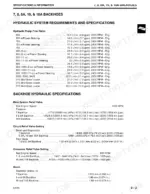
| Main System Relief Valve Pressure (7 Backhoe) | 11713 kPa (1700 psi) | p. 10 |
| Circuit Relief Valve Setting (7 Backhoe) | 14469 kPa (2100 psi) | p. 10 |
| 8 & 8A Backhoe | ||
| Main System Relief Valve Pressure (8 & 8A Backhoe) | 14124.5 kPa (2050 psi) | p. 10 |
| 10A Backhoe | ||
| Main System Relief Valve Pressure (10A Backhoe) | 15847 kPa (2300 psi) | p. 10 |
| 8, 8A, 10, 10A Backhoe | ||
| Circuit Relief Valve Setting (8, 8A, 10, 10A Backhoe) | 19981 kPa (2600 psi) | p. 10 |
| 7, 8, 8A Backhoe | ||
| Crossover Relief Valve Setting (7, 8, 8A Backhoe) | 7407-8440 kPa (1075-1225 psi) | p. 10 |
| 10, 10A Backhoe | ||
| Crossover Relief Valve Setting (10, 10A Backhoe) | 10335-11369 kPa (1500-1650 psi) | p. 10 |
John Deere 8A–390 Hydraulic Attachments Common Problems This Manual Covers
John Deere 8A backhoe hydraulics completely dead, no cylinder movement even with pump running at full throttle
Check reservoir oil level and pull the pickup screen before condemning the pump. Test main system relief pressure against the specs on page 10; the 8A backhoe should hold 14124.5 kPa (2050 psi). If pressure checks good, work through the troubleshooting procedures starting on page 29 to isolate a stuck spool or internal leak.
Manual Section: Backhoes p. 29Loader lift arms settle from raised position, bucket drifts back under load overnight
Measure the drop rate with a loaded bucket at transport height. On 60, 70, and 70A loaders, anything past 10.4 mm/min (.41 in./min) on the lift cylinders means worn packings, per the limits on page 18. Inspect the load check valves and replace spool seals in the control valve; the loader section starts on page 50.
Manual Section: Loader p. 50Hydraulic pump whines and cavitates after oil change, attachment runs slow and jerky
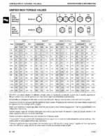
Check oil level first, then hunt for air leaks on the suction side. Retorque inlet fittings using the chart on page 19; a 3/8-24 UNF O-ring boss fitting takes only 8 Nm (6 lb-ft), so don't crank on it. Clean the reservoir vent cap and inspect the suction screen for plugging before running the machine hard.
Manual Section: Specifications & Information p. 19Hydraulic hose ballooning or weeping at the crimp fitting on the boom circuit
Replace the hose rather than patching it. Size the replacement from the pressure chart on page 70: 3/8 inch single wire braid carries 2250 psi while double wire braid carries 4000 psi. Cut the old hose open and check the inner tube for erosion, then route the new line clear of pivot points and sharp edges.
Manual Section: Miscellaneous p. 70Bucket cylinder leaking oil at the rod seal, dipperstick creeps down during digging
Remove the cylinder and disassemble it on a clean bench. Replace the rod seal, piston packing, and wiper, then inspect the rod for scoring and pitting before reassembly. Tighten the cylinder repair bolt to 203 N·m (150 lb-ft) as called out on page 67, and cycle the cylinder slowly to purge air before loading it.
Manual Section: Backhoes p. 35Frequently Asked Questions
How do I troubleshoot a John Deere 70A loader that will not lift?
If the loader will not lift, check for low oil level, a clogged oil filter, or internal leaks in the control valve or cylinders. Ensure the engine speed is sufficient and that hydraulic connections are secure. Refer to the troubleshooting chart on page 52 for further guidance. p. 52
What is the torque specification for the 44 Loader control valve plug?
When servicing the load check valve on a 44 Loader, the plug should be torqued to 20—27 N·m (15—20 lb-ft). p. 55
What is the procedure for testing the main system relief valve on a 7, 8, 8A, or 10A backhoe?
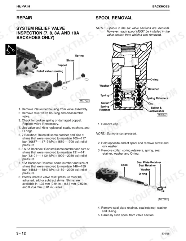
To test the main system relief valve, heat the hydraulic oil to 37.7—43.3°C (100—110°F), operate the engine at 1500 rpm, and move the boom function lever to its limit. The pressure specifications for the 7 Backhoe are 11713 kPa (1700 psi), for the 8 & 8A Backhoe are 14124.5 kPa (2050 psi), and for the 10A Backhoe are 15847 kPa (2300 psi). p. 34
What is the torque specification for the lock nut on a 7 Backhoe bucket cylinder?
When reassembling the bucket cylinder on a 7 Backhoe, the lock nut must be tightened to 271 N·m (200 lb-ft). p. 42
What is the correct hydraulic oil to use for the tiller transmission?
Use John Deere HY-GARD (J20C) transmission and hydraulic oil. Use J20C when ambient temperatures are above -18°C (0°F) and J20D low viscosity HY-GARD when temperatures are below -18°C (0°F). p. 23
How quickly can I access this John Deere 8A manual after buying?
A 73-page Technical Manual in searchable PDF format, available the moment you complete checkout. View on computer, tablet, or phone, with no shipping wait.
Can I print just the pages I need from this John Deere 8A manual?
Yes. Print the pages you need for the job in your own shop, and bin them when they get greasy.







Reviews
There are no reviews yet.