


Part of the John Deere Repair Manuals.
Need the factory teardown specs for your John Deere 300D, 310D, or 315D? This 876-page repair manual (OEM #TM1497) covers every system across all three backhoe loaders in a single volume. Inside: full hydraulic schematics for the main pump, loader, and backhoe circuits, backed by exploded views and a torque section with fastener specs for every critical assembly. You get page after page of step-by-step procedures walking through removal, rebuild, and reinstallation, from the MFWD axle and power shift clutch all the way to the operator cab and backhoe bucket. Torque the main hydraulic pump cap screws to 88-102 N·m (65-75 lb-ft); snug the 300D bucket cylinder piston nut to 100 N·m, then turn it an additional 30 degrees. No more digging through dealer printouts for a basic fastener spec. Download, search by keyword, and bring it right to the machine.
What's Inside This John Deere 300D, 310D, 315D Repair Manual
| System | Pages | Key Topics |
|---|---|---|
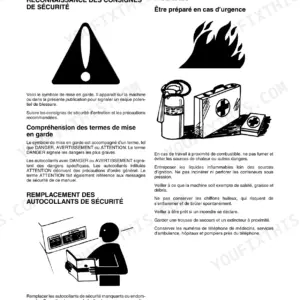
| General Information | 8-66 | Safety Information, Handle Fluids Safely-Avoid Fires, Prevent Battery Explosions, Prepare for Emergencies, Prevent Acid Burns, Handle Chemical Products Safely, Avoid High-Pressure Fluids |
| Wheels | 67-84 | Powered Wheels and Fastenings, Non-Powered Wheels and Fastenings |
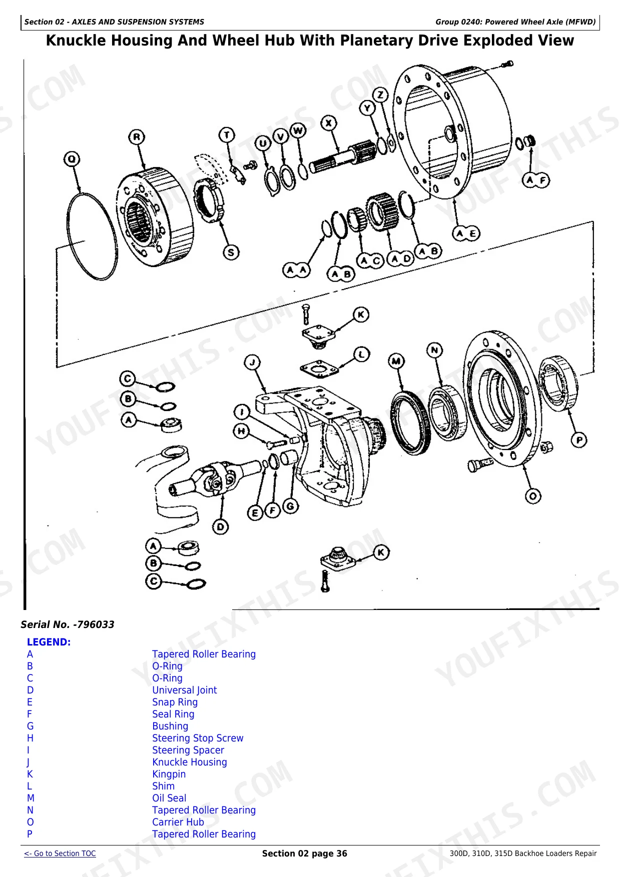
| Axles and Suspension Systems | 85-215 | Input Drive Shafts and U-Joints, Non-Powered Wheel Axles, Powered Wheel Axle, MFWD, Axle Shaft, Bearings, And Reduction Gears |
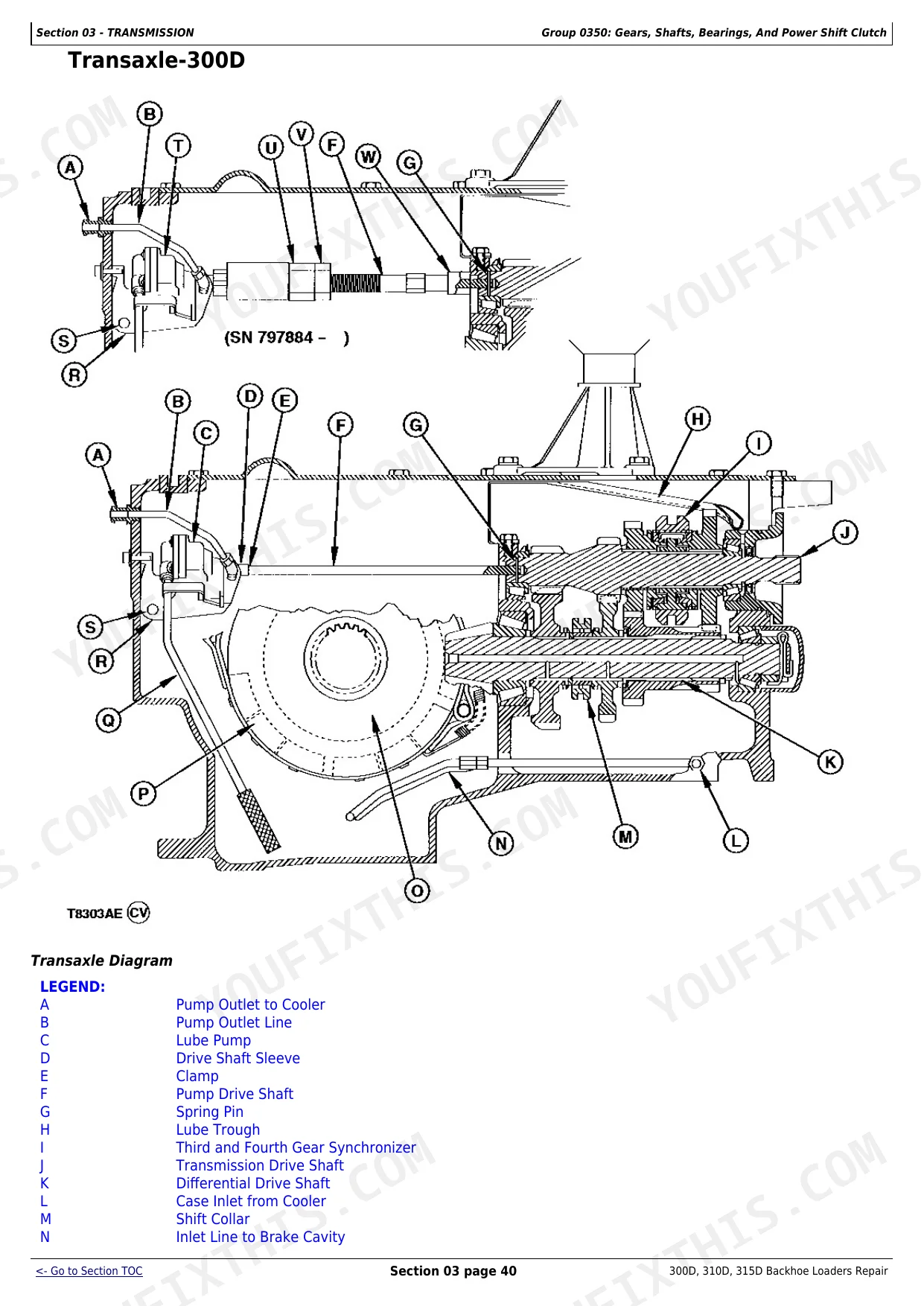
| Transmission | 216-335 | Transmission Controls Linkage, Input Drive Shafts and U-Joints, Gears, Shafts, Bearings, And Power Shift Clutch |
| Engine | 336-353 | Engine Removal and Installation |
| Engine Auxiliary Systems | 354-374 | Cold Weather Starting Aids, Cooling Systems, Speed Controls, Intake System, External Fuel Supply System |
| Torque Converter | 375-377 | Turbine, Gears and Shaft |
| Steering System | 378-419 | Steering Hydraulic System |
| Service Brakes | 420-453 | Service Brakes Active Elements, Service Brakes Hydraulic System, Dealer Fabricated Tools |
| Park Brake | 454-477 | Park Brake Active Elements, Park Brake Hydraulic System |
| Electrical Systems | 478-518 | Batteries, Support and Cables, Alternator, Regulator and Charging System Wiring, Lighting System, Wiring Harness and Switches |
| Frames, Chassis or Supporting Structure | 519-527 | Frame Installation, Chassis Weights |
| Operator’S Station | 528-618 | Operator Enclosure, Seat and Seat Belt, Heating and Air Conditioning |
| Sheet Metal and Styling | 619-629 | Hood and Engine Enclosure, Miscellaneous Shields, Grille and Grille Housing, Fenders |
| Safety, Convenience and Miscellaneous | 630-635 | Radio, Horn and Warning Devices |
| Main Hydraulic System | 636-672 | Main Hydraulic Pump, Priority Valve, Hydraulic Filter, Hydraulic Reservoir, Pump Drive Shaft Assembly |
| Loader | 673-743 | Bucket, Loader Controls Linkage, Frames, Loader Hydraulic System, Dealer Fabricated Tools |
| Backhoe | 744-876 | Bucket, Control Linkage, Frames, Backhoe Hydraulic System |
Quick Reference Specifications
| Specification | Value | Page |
|---|---|---|
| Main Hydraulic Pump (SN -802199) Pump Section Cap Screws and Threaded Studs Torque | 88-102 N·m (65-75 lb-ft) | p. 636 |
| Main Hydraulic Pump (SN -802199) Steering Pump Section Cap Screws Torque | 54-68 N·m (40-50 lb-ft) | p. 636 |
| Bucket Cylinder-300D Piston Nut Snug Torque | 100 N·m (74 lb-ft) | p. 739 |
| Bucket Cylinder-300D Piston Nut Torque Turn | 1/12 turn (30°) | p. 739 |
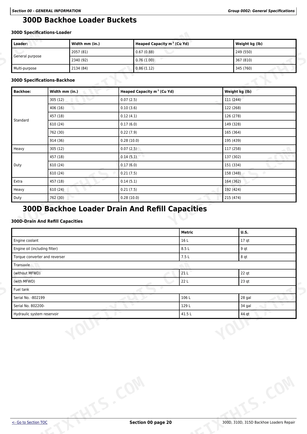
| Engine Coolant Capacity | 16 L (17 qt) | p. 337 |
| Loader Control Valve (SN 802200- ) Mounting Cap Screws Torque | 37 N·m (27 lb-ft) | p. 691 |
| Loader Control Valve (SN 802200- ) Tie Rod Nuts Torque | 54 N·m (40 lb-ft) | p. 691 |
| Hydraulic System Return Oil Filter | 10 micron replaceable element | p. 26 |
| Filter Mounting Cap Screw Torque | 33 ± 4 N·m (24 ± 3 lb-ft) | p. 636 |
| Hydraulic System Pressure Setting | 2700 psi (18 620 kPa) | p. 26 |
John Deere 300D, 310D, 315D Common Problems This Manual Covers
Engine overheats during extended digging cycles, coolant temp gauge pegs red
Verify coolant level; system holds 16 L (17 qt) per page 337. Inspect fan belt deflection: new belt spec is 8 mm at 111 N (5/16 in. at 25 lb force). Adjust via the alternator strap and torque the strap cap screw to 27 ± 3 N·m (20 ± 2 lb-ft) per page 361. Clean the radiator core and test thermostat.
Manual Section: Engine Auxiliary Systems p. 361Backhoe boom and dipper sluggish under load, dig force noticeably reduced
Measure backhoe circuit relief pressures. On 300D, crowd out (B) should hold 22 000 kPa (3200 psi); on 310D/315D verify 24 100 kPa (3500 psi) per page 808. If a relief valve is venting early, clean or replace it. Inspect the backhoe control valve for worn spools; rebuild per the Backhoe section at page 744.
Manual Section: Backhoe p. 808Engine cranks slowly or won't start in cold weather below freezing
Load-test the battery. Minimum spec is 625 cold cranking amps at -18°C per page 478. Check electrolyte level and hydrometer reading on each cell; verify terminal connections are clean and tight. If the battery fails load test, replace it. Inspect cold weather starting aids per Engine Auxiliary Systems at page 354.
Manual Section: Electrical Systems p. 478Boom cylinder leaks past seals, arm slowly loses height when idle
Remove and disassemble the cylinder per page 744. Inspect bore, rod, and seals for scoring. Torque boom piston nuts per page 739: 300D snugs at 100 N·m (74 lb-ft); 310D/315D snugs at 250 N·m (185 lb-ft), both require an additional angle turn. Torque rod guide spanner nuts to 173-237 N·m (128-175 lb-ft) per page 792.
Manual Section: Backhoe p. 792Frequently Asked Questions
What are the torque specs for hydraulic pump bolts on John Deere 310D?
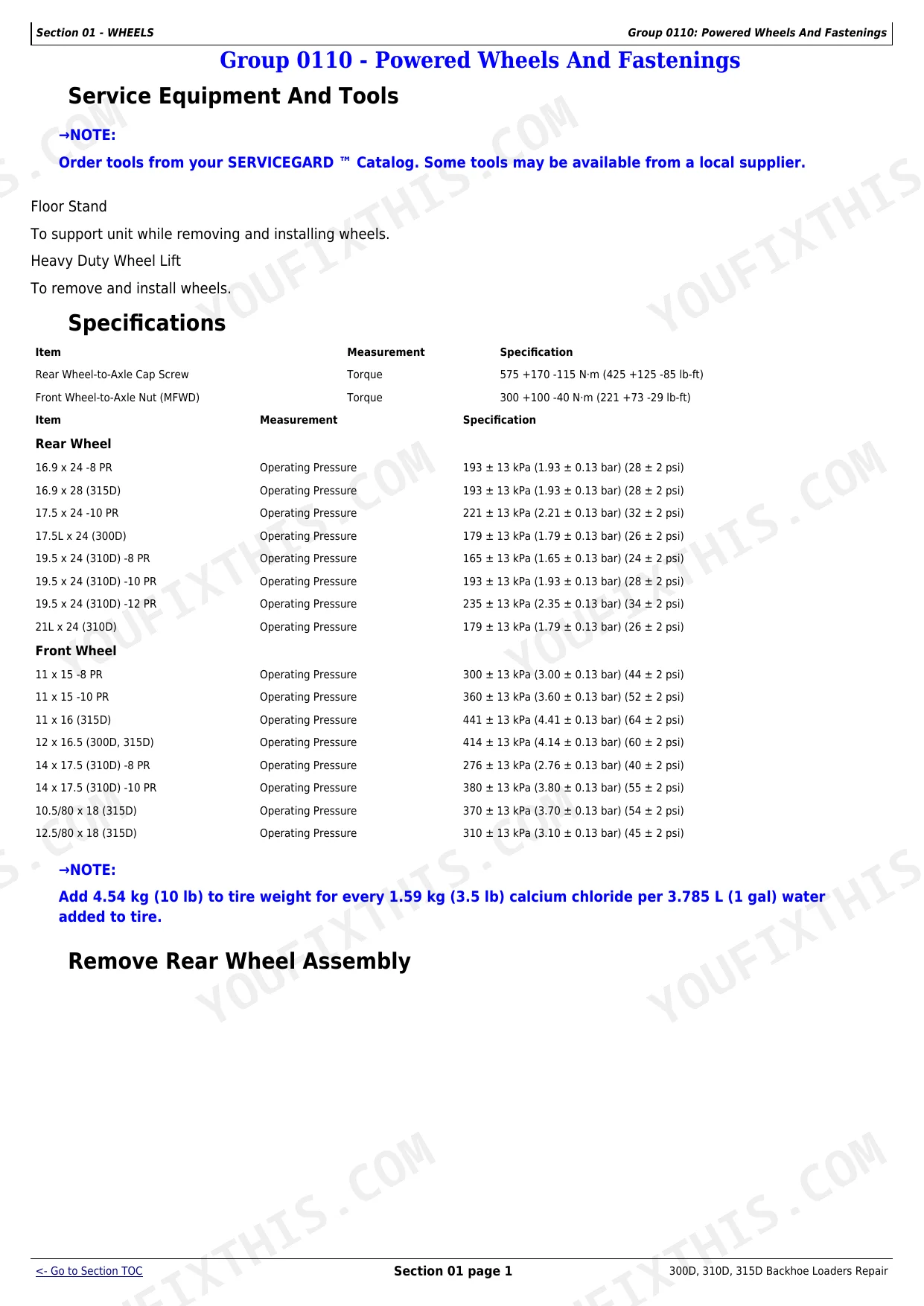
For the Main Hydraulic Pump (SN -802199), pump section cap screws and threaded studs should be torqued to 88-102 N·m (65-75 lb-ft). For Main Hydraulic Pump (SN 802200- ), the pump housing nut torque is 272 N·m (200 lb-ft), and auxiliary pump-to-main pump cap screws are torqued to 193 N·m (142 lb-ft). Additionally, reverser charge pump cap screws require a torque of 23-30 N·m (17-22 lb-ft). p. 636
What are the replacement specifications for Hydraulic pump?
For the Main Hydraulic Pump (SN 802200- ), only seals are serviceable. If any other parts are found worn or damaged, the entire pump must be replaced. It is also important to lubricate all internal surfaces with clean hydraulic oil before assembly, as premature pump failure can result if the pump is assembled dry. p. 643
How do you fix john Deere 310D hydraulic system pressure drops after 2-3 hours, backhoe slows down?
Check hydraulic reservoir level; capacity is 41.5 L (44 qt) per page 27. Inspect the 10-micron return oil filter for clogging and replace if overdue. Measure system pressure at the main relief valve: spec is 2700 psi (18 620 kPa) per page 26. If pressure reads low, pull the pump for inspection per the Main Hydraulic System section at page 636. p. 636
How do you fix loader bucket drifts down slowly with engine off, won't hold position?
Inspect loader control valve spools for wear or internal bypass; disassemble and clean per the Loader section at page 673. Torque 27 mm relief valves to 65 N·m (48 lb-ft) and 22.2 mm relief valves to 45 N·m (33 lb-ft) per page 691. Check loader cylinder seals for bypass before reassembling the valve. p. 691
How quickly can I access this John Deere 300D, 310D, 315D manual after buying?
Instant PDF download. You get the full 876-page searchable Repair Manual immediately after payment. Open it on your laptop, tablet, or phone right in the shop.
Are there any print restrictions on this John Deere 300D, 310D, 315D manual?
None at all. The PDF is DRM-free. Print whatever sections you need to take out to the shop. Standard letter or A4 paper works.
Does this John Deere 300D, 310D, 315D Repair Manual cover the hydraulic system?
Yes. The manual includes hydraulic circuit diagrams, system schematics, and component specifications with pressure ratings.