

Part of the John Deere Repair Manuals.
TM1564 is the factory repair manual John Deere issued in February 1995 for the 2700, 2800 and 2900 tractors, and it is the one you want open on the bench when the tractor is split in half. Eleven sections across 1120 pages walk through the 4.2 L four cylinder turbo engines (Z1201T, Z1001T, Z1301A), the mechanical shift transmission, final drive, hydrostatic steering, brakes and the full hydraulic system with ISO circuit schematics. Section 15 covers separating the transmission from the engine with the special tools listed, and Section 40 carries complete harness diagrams with wire colours and numbers. This is a repair manual, not an operator booklet: teardown, inspection specs and reassembly for every major assembly.
What's Inside This John Deere 2700, 2800, 2900 Manual
| System | Pages | Key Topics |
|---|---|---|
| Safety | 7-20 | Safety Precautions |
| General Information | 21-43 | Specifications, Fuels, Lubricants and Coolant |
| Component Removal and Installation | 44-102 | Special Tools and Specifications, Separate Transmission From Engine, Clutch and PTO Housing, Transmission, Engine |
| Engine Repair | 103-419 | Clutch, Engine Mounting, Cylinder Head and Valves, Pistons Rods and Liners, Crankshaft and Bearings, Camshaft Balancer Shafts and Timing Gear Train, Cooling System, Air Intake and Exhaust, Fuel System, Oil Pump, Air Compressor |
| Electrical Repair | 420-557 | System Diagrams and Schematics, Battery, Harness Repair, Alternator, Starting Motor, Lights, Instruments and Switches, Sensors |
| Mechanical Shift Transmission | 558-687 | Special Tools, Clutch and PTO Housing, Transmission Cover, Gears and Shafts |
| Power Train Final Drive | 688-759 | Reduction Gears, PTO Assembly, Rear Half Axle, Differential |
| Brakes and Steering | 760-913 | Hydrostatic Steering Operation, 2WD Front Axle, Hydrostatic Steering Motor, Steering Cylinder, Steering Pump, Brakes, Trailer Air Brake System |
| Hydraulics | 914-1022 | Testing Hydraulic System, Hydraulic System Operation, Main Hydraulic Pumps, Servicing Transmission and Hydraulic System, Rockshaft, Hydraulic Pump Control and Drive Unit |
| Miscellaneous | 1023-1042 | Wheels and Tires, Ballast |
| Operator Station | 1043-1113 | Seat, Open Station Platform |
Quick Reference Specifications
| Specification | Value | Page |
|---|---|---|
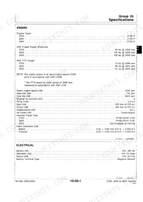
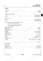
| Engine (2700) | Z1201T, four cylinder turbocharged, 4.2 L | p. 21 |
| Engine (2800) | Z1001T, four cylinder turbocharged, 4.2 L | p. 21 |
| Engine (2900) | Z1301A, four cylinder turbocharged, 4.2 L | p. 21 |
| SAE Engine Power at Flywheel | 2700 89 hp, 2800 100 hp, 2900 106 hp at 2200 rpm | p. 21 |
| SAE PTO Power | 2700 75 hp, 2800 86 hp, 2900 91 hp at 2200 rpm | p. 21 |
| Bore and Stroke | 105 mm (4.133 in.) x 120 mm (4.724 in.) | p. 21 |
| Valve Clearance (intake and exhaust) | 0.25 ± 0.05 mm (0.012 ± 0.002 in.) | p. 21 |
| Electrical System | 12 V 180 Ah battery, negative ground, 14 V 55 amp alternator, 12 V 3.5 kW starter | p. 21 |
| Fuel Tank Capacity | 105 L (27.7 gal) | p. 22 |
| Engine Crankcase Capacity | 10 L (10.5 qts) | p. 22 |
| Transmission and Rear Axle Capacity | 38.9 L (42 qts) | p. 22 |
| Hydrostatic Steering Capacity | 4.5 L (4.8 qt) | p. 22 |
| Average Shipping Weight (4WD with cab) | 2700 3323 kg (7327.2 lbs.); 2800 and 2900 3456 kg (7620.5 lbs.) | p. 23 |
John Deere 2700, 2800, 2900 Common Problems This Manual Covers
Engine runs but the tractor will not move, or drive is lost under load
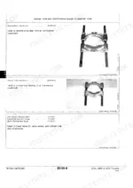
Start with Section 15, Separate Transmission from Engine, to open the tractor with the listed special tools, inspect the clutch, then follow Section 50 for the transmission gears and shafts and Section 55 for reduction gears and differential if the clutch checks out.
Manual Section: Component Removal and Installation / Mechanical Shift Transmission p. 44Starter does not work or the engine will not turn over
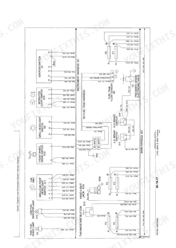
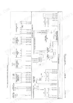
Use the system diagrams in Section 40 Group 10 to trace the start circuit by wire colour and number from the 12 V 180 Ah battery through the switch to the 3.5 kW starting motor, then follow the battery, harness repair and starting motor groups in the same section for testing and rebuild.
Manual Section: Electrical Repair / System Diagrams and Schematics p. 445Hydraulics or rockshaft weak, slow to lift, or will not hold an implement
Run the procedures in Section 70, Testing Hydraulic System, before pulling anything, and compare readings against the printed relief settings of 160/180 bar on the rockshaft circuit and 210 bar on the steering supply, then move to the main pump and rockshaft groups only if the numbers say so.
Manual Section: Hydraulics / Testing Hydraulic System p. 930Low power, black smoke, or the engine falls off under load
Work through Section 20, Fuel System and Air Intake and Exhaust, checking delivery from the 105 L tank through the injection pump and the turbocharger side, and confirm the engine still reaches its speeds of 700 rpm slow idle, 2200 rated and 2640 fast idle.
Manual Section: Engine Repair / Fuel System p. 21Frequently Asked Questions
My 2800 runs fine but will not move when I let the clutch out. Does this manual help me find out if it is the clutch or the transmission before I split the tractor?
Yes. Section 15 (Component Removal and Installation) gives the procedure for separating the transmission from the engine and pulling the clutch and PTO housing, with the special tools and specifications listed up front. Section 50 (Mechanical Shift Transmission) then covers the transmission cover, gears and shafts, and Section 55 handles the final drive, reduction gears and differential if the fault turns out to be behind the gearbox. You can work through the drive line in order instead of guessing. p. 44
The starter clicks or does nothing at all. Are there real wiring diagrams in here, with wire colours, or just a block sketch?
Section 40 Group 10 carries full system diagrams and schematics with wire colours and numbers, so you can trace the battery, cable and switch circuit to the starting motor wire by wire. The same section covers battery testing, harness repair, the 12 V 3.5 kW starter and the 55 amp alternator. This is a 1990s tractor with no fault codes and no diagnostic display, so the harness diagram and a test lamp are how you find it, and the manual is built for exactly that. p. 445
The rockshaft lifts slow and drops under load. Can I actually test the hydraulic system with this manual or does it just show parts?
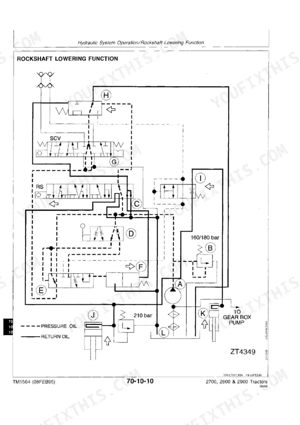
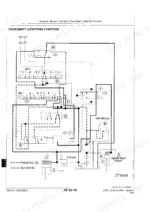
Section 70 opens with Testing Hydraulic System before any teardown, then explains system operation, the main hydraulic pumps, the rockshaft and the pump control and drive unit. The ISO circuit schematics use pressure and return oil keys, and the Rockshaft Lowering Function schematic prints the relief settings: 160/180 bar on the rockshaft circuit and 210 bar on the steering supply. So you test against numbers first, then decide between pump wear, relief setting or tired oil. p. 930
Does it cover a full engine rebuild, with the specs I need for the head and bottom end?
Section 20 is a complete engine repair section: cylinder head and valves, pistons, rods and liners, crankshaft and bearings, camshaft, balancer shafts and timing gear train, cooling, air intake and exhaust, fuel system, oil pump and even the air compressor. Base specs are in the manual too, for example valve clearance at 0.25 plus or minus 0.05 mm (0.012 plus or minus 0.002 in.) intake and exhaust, on the 105 mm bore, 120 mm stroke four cylinder with 1-3-4-2 firing order. p. 21
Which machines does TM1564 fit, and what form does the manual come in?
It covers the John Deere 2700 (89 hp), 2800 (100 hp) and 2900 (106 hp) tractors, all with the 4.2 L turbocharged four cylinder rated at 2200 rpm, in both 2WD and 4WD form, open station or cab. It is a scanned copy of the 1995 factory manual, 1120 pages, so treat it like the paper book: use the section layout (05 through 90) and the table of contents to navigate rather than expecting a text search. p. 3








Reviews
There are no reviews yet.