

Part of the John Deere Repair Manuals.
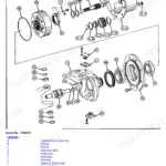
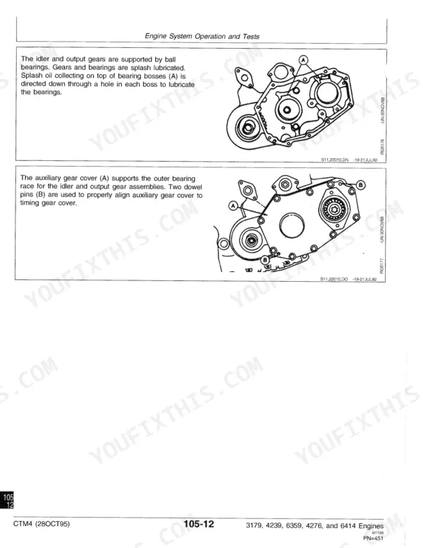
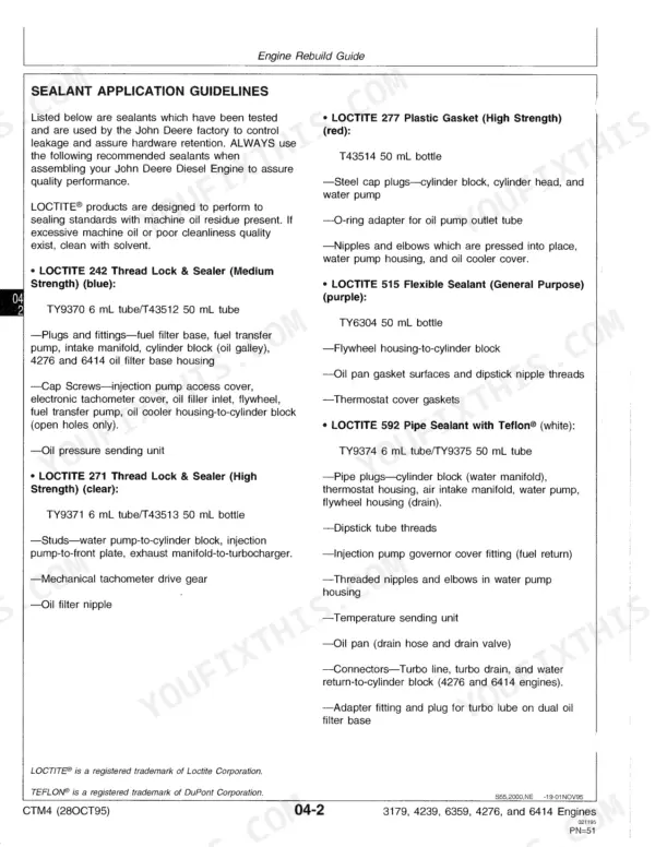
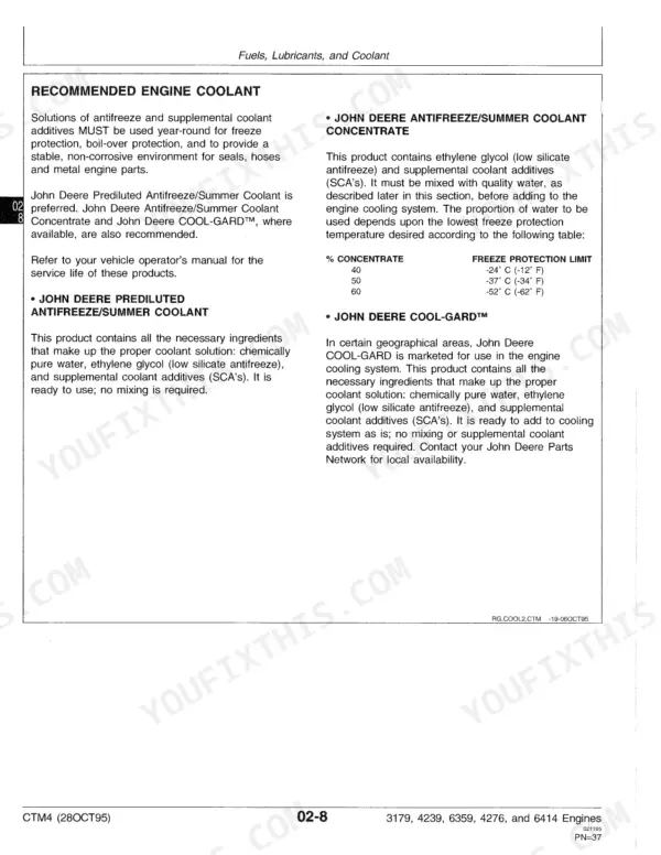
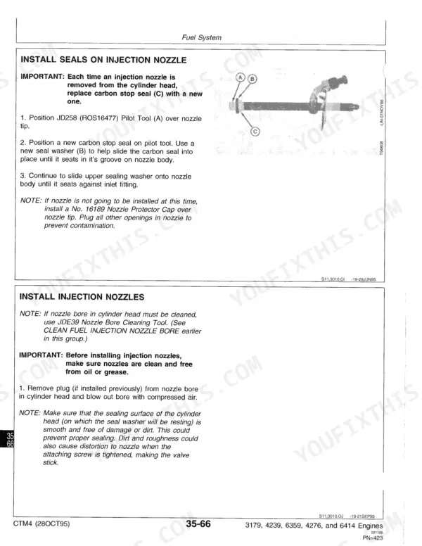
Finding the right specs for your rebuild is easy with this 547-page John Deere 4239 technical manual pdf, which also covers the 3179, 6359, 4276, and 6414 diesel engines (OEM CTM4). Inside, you get complete teardown procedures for the cylinder block, liners, and pistons, plus a full troubleshooting section to track down rough running conditions. Open to detailed exploded views of the timing gear train and heavy-duty torque tables for every critical fastener. Disconnect the turbocharger oil inlet line from the oil filter housing before rolling the engine over on your stand, and verify the updated dynamic timing values for the fuel injection pump. Stop tearing down blocks blind. Download this bookmarked file, search for your specific engine model by keyword, and get back to turning wrenches.
What's Inside This Manual
| System | Pages | Key Topics |
|---|---|---|
| Foley Part 1 | 3-84 | Unified Inch Bolt and Cap Screw Torque Values, Metric Bolt and Cap Screw Torque Values, Engine Model Designation, Engine Serial Number Plate Information, Engine Application Chart |
| Cylinder Head and Valves | 85-102 | Valve Seat Inserts, Valve Stem Seals, Cylinder Head Flatness, Cylinder Liner Standout, Cylinder Head Installation, Engine Break-In |
| Cylinder Block, Liners, Pistons, and Rods | 104-152 | Piston and Rod Removal, Cylinder Liner Inspection, Piston Ring Groove Wear, Piston-To-Liner Clearance, Cylinder Block Flatness, Steel Ball Installation |
| Crankshaft, Main Bearings, and Flywheel | 154-201 | Crankshaft Specifications, Vibration Damper, Flywheel removal/installation, Oil Seal Replacement, Main Bearing Clearance, Piston Cooling Orifices |
| Camshaft, Balancer Shafts, and Timing Gear Train | 202-252 | Camshaft Specifications, Balancer Shaft Specifications, Timing Gear Backlash, Valve Lift, Engine Front Plate Replacement, Fuel Injection Pump Timing Mark |
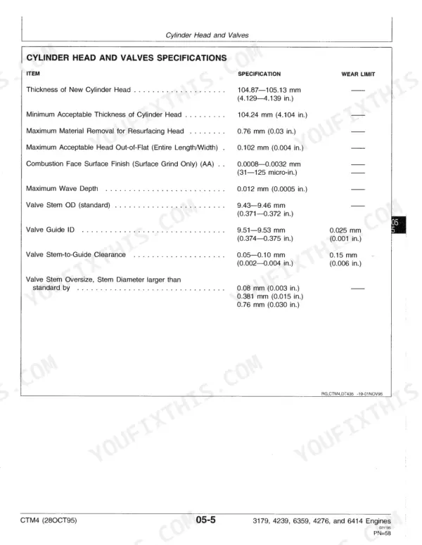
| Foley Part 3 | 339-458 | Cylinder Head and Valves Specifications, Torques, Rocker Arm Adjusting Set Screw, Cylinder Head Cap Screws, Fuel Injection Nozzles-to-Cylinder Head |
| Foley Part 4 | 459-547 | Cylinder Block, Liners, Pistons, And Rods Specifications, Torques, Piston Cooling Orifices Into Cylinder Block, Cylinder Liner Cap Screws, Connecting Rod Cap Screws |
Quick Reference Specifications
| Specification | Value | Page |
|---|---|---|
| Drive Shaft Bore (in pump housing) | 12.281-12.307 mm (0.4835-0.4845 in.) | p. 295 |
| Wear Limit (Drive Shaft Bore in pump housing) | 12.323 mm (0.4850 in.) | p. 295 |
| Impeller installation below surface of housing (all engines except 6359TF002 with option codes 2007 and 2302, 6414TT006, 6414TT007, 6414TT009 and 6414TT010) | 0.38 mm (0.015 in.) | p. 328 |
| Impeller installation to obtain clearance between inner side of impeller and housing (6359TF002 with option codes 2007 and 2302, 6414TT006, 6414TT007, 6414TT009 and 6414TT010) | 0.39-0.89 mm (0.015-0.035 in.) | p. 328 |
| Injection Pump Drive Shaft Seal Installer | JD256 | p. 365 |
| Nozzle Carbon Stop Seal Installer | JD258 | p. 365 |
| Injection Nozzle Puller | JDE38B | p. 366 |